Electromagnetic lens antenna

An electromagnetic lens and antenna technology, applied in antennas, electrical components and other directions, can solve the problems of limited size span, complex process precision requirements, etc., and achieve the effect of overcoming the inability to manufacture large-area metamaterial panels

Active Publication Date: 2013-01-23
KUANG CHI INST OF ADVANCED TECH +1
View PDF3 Cites 13 Cited by
  • Summary
  • Abstract
  • Description
  • Claims
  • Application Information

AI Technical Summary

Problems solved by technology

[0010] The technical problem to be solved by the present invention is that, in order to manufacture a large-area planar metamaterial panel in order to manufacture a large-area planar metamaterial panel in the prior art, the process of manufacturing a convex lens antenna is complicated, the precision requirement is high, and the ordinary anisotropic planar metamaterial lens antenna is processed. The size span is required to be relatively large, but the size of the artificial microstructure itself is limited by its principle and its size span is limited. A new type of electromagnetic lens antenna with anisotropic metamaterial panels is proposed, in which the anisotropic metamaterial The dimensions of the artificial microstructures of the material panels need only vary within a small range

Method used


Image

  • Electromagnetic lens antenna
  • Electromagnetic lens antenna
  • Electromagnetic lens antenna

Examples


Embodiment Construction

[0029] The present invention will be described in detail below in conjunction with the accompanying drawings.

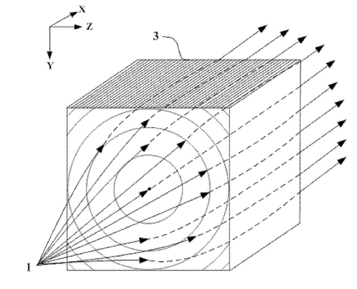
[0030] Such as image 3 As shown, the electromagnetic lens antenna with anisotropic metamaterial provided in this embodiment includes an anisotropic metamaterial panel 3 with converging function and a radiation unit 1 located at the focal point of the metamaterial panel 3, and the radiation unit 1 is located in the middle In the direction of the central axis of the metamaterial panel at the position, the metamaterial panel 3 is composed of multiple metamaterial sheets stacked together along the Z-axis direction, and the metamaterial sheets are arranged and assembled at equal intervals or adjacent sheets are attached to each other. Stacked as a whole, each metamaterial sheet is composed of a sheet-like substrate and an artificial microstructure attached to the substrate. Each substrate is virtually divided into multiple identical cubic substrate units that are next to...


PUM


Abstract

The invention provides an electromagnetic lens antenna; and the electromagnetic lens antenna comprises an aeolotropic metamaterial panel and a radiation unit, wherein the metamaterial panel has an aggregation function, and the radiation unit is positioned at a focal point of the metamaterial panel; the metamaterial panel comprises a cylindrical area and at least one barrel type area, which have the same central axis, when being looked in an incident direction of an electromagnetic wave; the refractive index in each area is symmetric relative to the central axis in a radial direction and gradually reduced with the increasing of the radius, and the variation rate of the refractive index is also gradually increased; the refractive index at the junction of the areas discontinuously varies; refractive index variation ranges of the different areas are intersected in a nonvoid way; the metamaterial panel is obtained by overlaying metamaterial sheet layers; each metamaterial sheet layer comprises a substrate and a plurality of artificial microstructures, wherein the artificial microstructures are attached to the substrate; the artificial microstructures are symmetric structures which cannot rotate 90 degrees; and extraordinary light optical axes of refraction index ellipsoids of the artificial microstructures are not vertical to each other and not parallel to the incident direction of the electromagnetic wave. Through the adoption of the electromagnetic lens antenna provided by the invention, the electromagnetic waves can be received or transmitted in an oriented way.

Description

technical field [0001] The invention relates to an electromagnetic lens antenna, in particular to an electromagnetic lens antenna with the function of converging electromagnetic waves. Background technique [0002] In conventional optical devices, a lens can be used to make the spherical wave radiated by a point light source placed at the focal point of the lens become a plane wave after being refracted by the lens. The lens antenna is composed of a lens and a radiator placed on the focal point of the lens. Using the characteristic of lens convergence, the electromagnetic wave emitted by the radiator is concentrated by the lens and then emitted. This antenna has strong directivity. [0003] At present, the convergence of the lens is realized by the refraction of the curved surface shape of the convex lens, such as figure 1 As shown, the spherical wave emitted by the radiator 1 is converged by the convex lens 2 and emitted as a plane wave. The convex lens 2 is large and heav...

Claims


Application Information

Patent Timeline
Patent Type & Authority Applications(China)
IPC IPC(8): H01Q15/00H01Q15/02
Inventor 刘若鹏王今金季春霖岳玉涛
Owner KUANG CHI INST OF ADVANCED TECH
Why Eureka
Try Eureka