Single-polarizer reflective bistable twisted nematic (btn) liquid crystal display device

a liquid crystal display device and single-polarizer technology, applied in non-linear optics, instruments, optics, etc., can solve the problems that the birefringent compensation layer developed to improve the contrast ratio and reduce the color shift at oblique viewing angles of tn displays is not suitable for use with btn displays, and achieves the effect of improving the optical performance of single-polarizer

Inactive Publication Date: 2009-08-27
FRANCE BREVETAB
View PDF5 Cites 4 Cited by
  • Summary
  • Abstract
  • Description
  • Claims
  • Application Information

AI Technical Summary

Benefits of technology

[0001]The present invention concerns the field of liquid crystal displays (LCDs) and more specifically a method for improving the optical performance of single-polarizer reflective bistable twisted nematic (πBTN) liquid crystal displays when viewed at oblique angles.

Problems solved by technology

For this reason birefringent compensation layers developed to improve contrast ratio and reduce color shift at oblique viewing angles for TN displays would not be suitable for use with BTN displays.

Method used


Image

  • Single-polarizer reflective bistable twisted nematic (btn) liquid crystal display device
  • Single-polarizer reflective bistable twisted nematic (btn) liquid crystal display device
  • Single-polarizer reflective bistable twisted nematic (btn) liquid crystal display device

Examples


example 1

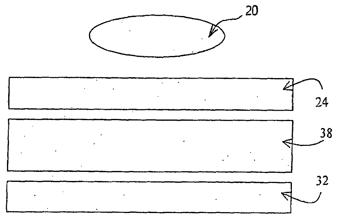
C+ Compensation Layer Between Polarizer with No TAC Substrate and πBTN Liquid Crystal Layer

[0114]For this example the polarizer has no birefringent TAC substrate. This example could correspond to any of the embodiments described in connection with FIGS. 16-18 but is particularly suited for the embodiment of FIG. 17 where the polarizer and compensation layer are located between the transparent substrate 120 and the πBTN liquid crystal layer 150. If the polarizer were deposited by a coating process, for example, a TAC substrate layer would not be present. For this configuration, the polarizer can be oriented either at −41.3° or at 48.7°. The optical performance of these two configurations are simulated, finding an optimum value for the C+ compensator, and the results are given in the table 6 where it is seen that configuration #1 gives a slightly wider viewing cone and slightly less color shift. The stack corresponding to configuration #1 is explicitly presented in table 7.

TABLE 6the ...

example 2

C+ Compensation Layer Between Polarizer with TAC Substrate and πBTN Liquid Crystal Layer

[0117]For this configuration a birefringent TAC layer has been added to the polarizer. As before, the polarizer can be oriented either at −41.3° or at 48.7°. The optical performance of these two configurations are simulated, finding an optimum value for the C+ compensator, and the results are given in the table 8 where it is seen that configuration #1 gives a slightly wider viewing cone and slightly less color shift. The stack corresponding to configuration #1 is explicitly presented in table 9.

TABLE 8the oblique optical performance of mode 1-1 of the single-polarizer reflective πBTN display with one TAC layer andan optimized positive C retarder between the TAC layerand the πBTN LC layer.Config.TACPositive CNo.P angle(nz − no) · d(nz − no) · dΔCmaxθmax#1−41.3−55 nm120 nm0.461°#2  48.7°−55 nm115 nm0.659°

TABLE 9configuration #1 of πBTN optical compensation with one TACsubstrate and an optimized pos...

example 3

Polarizer with TAC Substrate and C+ Compensation Layer Between πBTN Liquid Crystal Layer and the Reflector

[0120]In this example the compensator is located on the other side of the πBTN layer between the πBTN layer and the reflector. This example could take the form of the embodiments described in connection with FIG. 19. For this configuration, the polarizer can be oriented either at −41.3° or at 48.7°. The optical performance of these two configurations are simulated, finding an optimum value for the C+ compensator, and the results are given in the table 10 where it is seen that configuration #2 gives slightly larger θmax and slightly less maximum color shift ΔCmax. The stack corresponding to configuration #2 is explicitly presented in table 11.

TABLE 10the oblique optical performance of mode 1-1 of the single-polarizer reflective πBTN display with one TAC layer andan optimized C+ retarder between the πBTN liquidcrystal layer and the reflector.Config.TACPositive CNo.P angle(nz − no)...


PUM

PropertyMeasurementUnit
angleaaaaaaaaaa
angleaaaaaaaaaa
twist angleaaaaaaaaaa

Abstract

The application relates to a single-polarizer reflective bistable twisted nematic (BTN) liquid crystal display device comprising a liquid crystal layer of thickness d, birefringence Δn and retardation Δnd, said liquid crystal layer being situated between two substrates and between a polarizer and a reflector, said liquid crystal layer in the absence of an applied electric field having two stable uniformly twisted textures, the twists of the two stable textures differing by an angle being equal mainly to 180°, and at least one compensation layer positioned between said polarizer and said reflector, said compensation layer being composed of at least one birefringent film, said birefringent film having an optical anisotropy defined by three characteristic refractive indices nx, ny, nz, along three corresponding axis x, y, z of index ellipsoid, x and y being situated inside the substrates plane, nx and ny being called in plane indices, with nx≧ny, x being called slow axis, and z being perpendicular to the substrates plane with biaxiality parameter Nz equal to (nx−nz)/(nx−ny), characterized in that Nz lies between −∞ and ½ so that under oblique viewing the retardation of the stable texture corresponding to the dark state is compensated to improve the contrast ratio and simultaneously the retardation of the stable texture corresponding to the bright state is modified to decrease the color shift.

Description

FIELD AND OBJECT OF THE INVENTION[0001]The present invention concerns the field of liquid crystal displays (LCDs) and more specifically a method for improving the optical performance of single-polarizer reflective bistable twisted nematic (πBTN) liquid crystal displays when viewed at oblique angles.BACKGROUND OF THE INVENTIONSingle-Polarizer Reflective LCDs[0002]Conventional LCDs used in liquid crystal television sets and desktop computer monitors are transmissive displays with polarizers on both sides of the LCD cell. A backlight provides the source of illumination. Such two-polarizer transmissive LCDs can be transformed into two-polarizer reflective LCDs simply by placing a reflector behind the rear polarizer. Ambient light from the front provides the illumination source. However, there are several problems associated with these two-polarizer reflective LCDs. One problem is the appearance of double-imaging when the display is observed obliquely. This is caused by parallax introduc...

Claims


Application Information

Patent Timeline
Patent Type & Authority Applications(United States)
IPC IPC(8): G02F1/13363G02F1/13
CPCG02F1/133634G02F2001/133567G02F2001/133531G02F1/1391G02F1/133531G02F1/133567
Inventor JOUBERT, CECILESCHEFFER, TERRY
Owner FRANCE BREVETAB
Why Eureka
Try Eureka