Drive device and spatial information detector device employing same

一种驱动装置、驱动信号的技术,应用在测量装置、辐射控制装置、图像通信等方向,能够解决时间变长、电荷量增加、延迟等问题

Inactive Publication Date: 2013-01-23
PANASONIC CORP
View PDF4 Cites 6 Cited by
  • Summary
  • Abstract
  • Description
  • Claims
  • Application Information

AI Technical Summary

Problems solved by technology

In this way, when the migration period is long, the time required for the overall operation may become longer and delay may occur, and the amount of charge lost due to recombination or the like during the transfer of charges may increase.

Method used


Image

  • Drive device and spatial information detector device employing same
  • Drive device and spatial information detector device employing same
  • Drive device and spatial information detector device employing same

Examples


Embodiment Construction

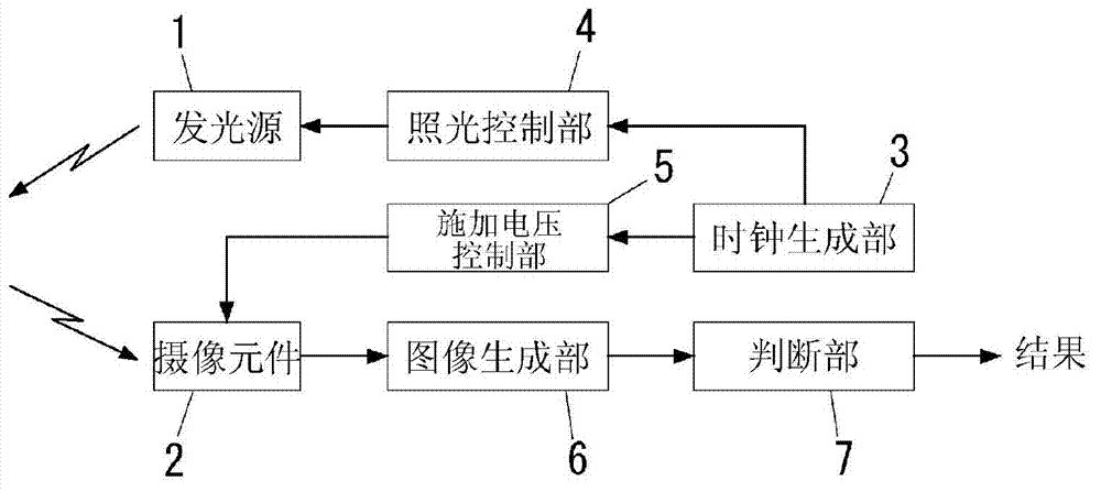
[0042] In the embodiment described below, if image 3 As shown, an imaging device including: a light emitting source 1 that irradiates light toward a target space; and an imaging element 2 that receives light from the target space is exemplified. exist image 3 A charge-coupled device is used as the imaging device 2. However, this configuration is an example, and is not intended to limit the configuration of the present invention.

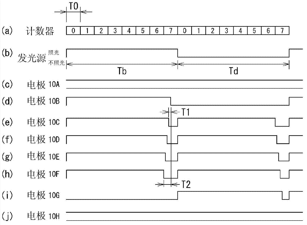
[0043] The light emitting source 1 is configured using a light emitting diode or a laser diode, and is driven based on an illumination signal generated by the illumination control unit 4 . The light-emitting signal is a signal for instructing the light-emitting source 1 to light or not to light every fixed cycle (eight cycles in this embodiment) of the clock signal output from the clock generator 3, and is a signal to the clock through the light-emitting control portion 4. The signal is generated by frequency division.

[0044] On the other han...


PUM


Abstract

A drive device comprises an impressed voltage controller unit that carries out a transfer process that controls a charge-coupled device and transfers an electric charge. The impressed voltage controller unit switches a voltage that is applied to an array of transfer electrodes, in sequence from a first end side to a second end side of the array of transfer electrodes of the charge-coupled element, from a control voltage that generates the potential well to a reference voltage that annihilates the potential well. The impressed voltage controller unit further comprises a control circuit that generates a drive signal on the basis of the clock signal, and a drive circuit that selectively applies the control voltage and the reference voltage to the transfer electrodes in accordance with the drive signal. With respect to a first drive signal, which is the drive signal that corresponds to one transfer electrode of adjacent transfer electrodes, the control circuit delays a second drive signal, which is the drive signal that corresponds to the other transfer electrode of the adjacent transfer electrodes, and sets the phase difference between the first drive signal and the second drive signal to a value corresponding to a prescribed time that is shorter than the period of the clock signal.

Description

technical field [0001] The present invention relates to a drive device of a charge coupled element that transfers charges using a potential well formed on a semiconductor forming the charge coupled element by controlling a control voltage applied to electrodes of the charge coupled element, and a device using the charge coupled element The spatial information detection device of the driving device. Background technique [0002] Generally, charge-coupled devices (CCD=Charge-Coupled Devices) are used in fields such as image sensors, analog signal delays, and digital signal shift registers. In such a charge-coupled device, a plurality of electrodes are arranged on the surface of an element formation layer formed of a semiconductor, and charges are accumulated in potential wells formed in the element formation layer by applying a control voltage to each electrode. In addition, by controlling the control voltage applied to the arranged electrodes, the positions and depths of the...

Claims


Application Information

Patent Timeline
Patent Type & Authority Applications(China)
IPC IPC(8): H04N5/372H01L27/148G01S7/4865G01S17/89
CPCH04N5/37213G01S17/89H04N5/3765G01S7/4865G01S17/88H04N25/713H04N25/745H01L27/148H04N25/71H01L27/14856H01L27/14806
Inventor 栗原史和桥本裕介
Owner PANASONIC CORP
Why Eureka
Try Eureka