Motor drive method

A driving method and motor technology, applied in the direction of electronically commutated motor control, single motor speed/torque control, electrical components, etc., can solve the problems of areas where the rotor position cannot be detected, reverse rotation or deviation from the same step, and failure to start. To achieve good quality, shorten the period, improve the effect of starting speed

Inactive Publication Date: 2007-08-29
PANASONIC CORP
View PDF4 Cites 6 Cited by
  • Summary
  • Abstract
  • Description
  • Claims
  • Application Information

AI Technical Summary

Problems solved by technology

Therefore, it is difficult to apply when obtaining autonomous controllability or an inexpensive motor drive system from the motor.
[0016] In Patent Document 3, there is a problem that there is an area where the rotor position cannot be detected
In this area, the motor stops when starting, no matter how the rotor search pulse is applied, the motor may be in a stopped state, resulting in the problem of not being able to start
In addition, when the rotor position cannot be detected correctly like this, even if the initial position search process of the rotor position is switched to the reverse induced voltage mode, there is a problem of reverse or step deviation.

Method used


Image

  • Motor drive method
  • Motor drive method
  • Motor drive method

Examples


no. 1 approach

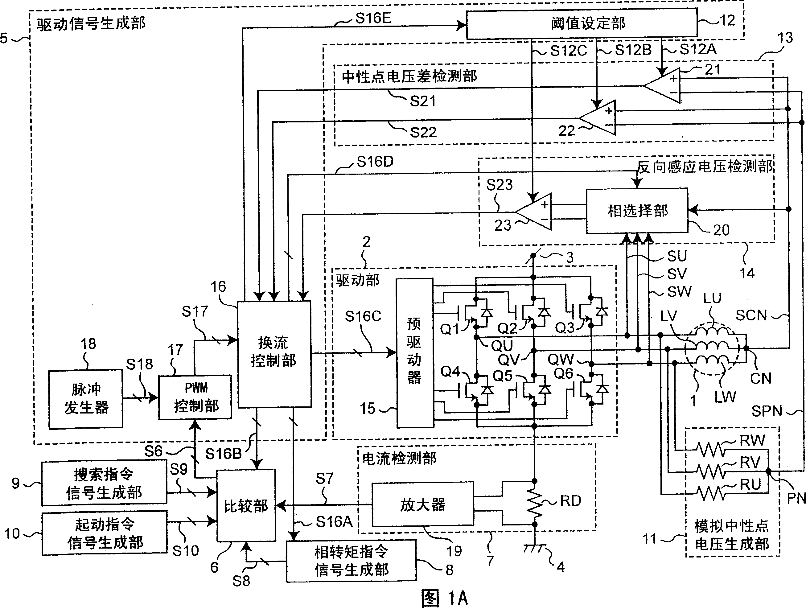
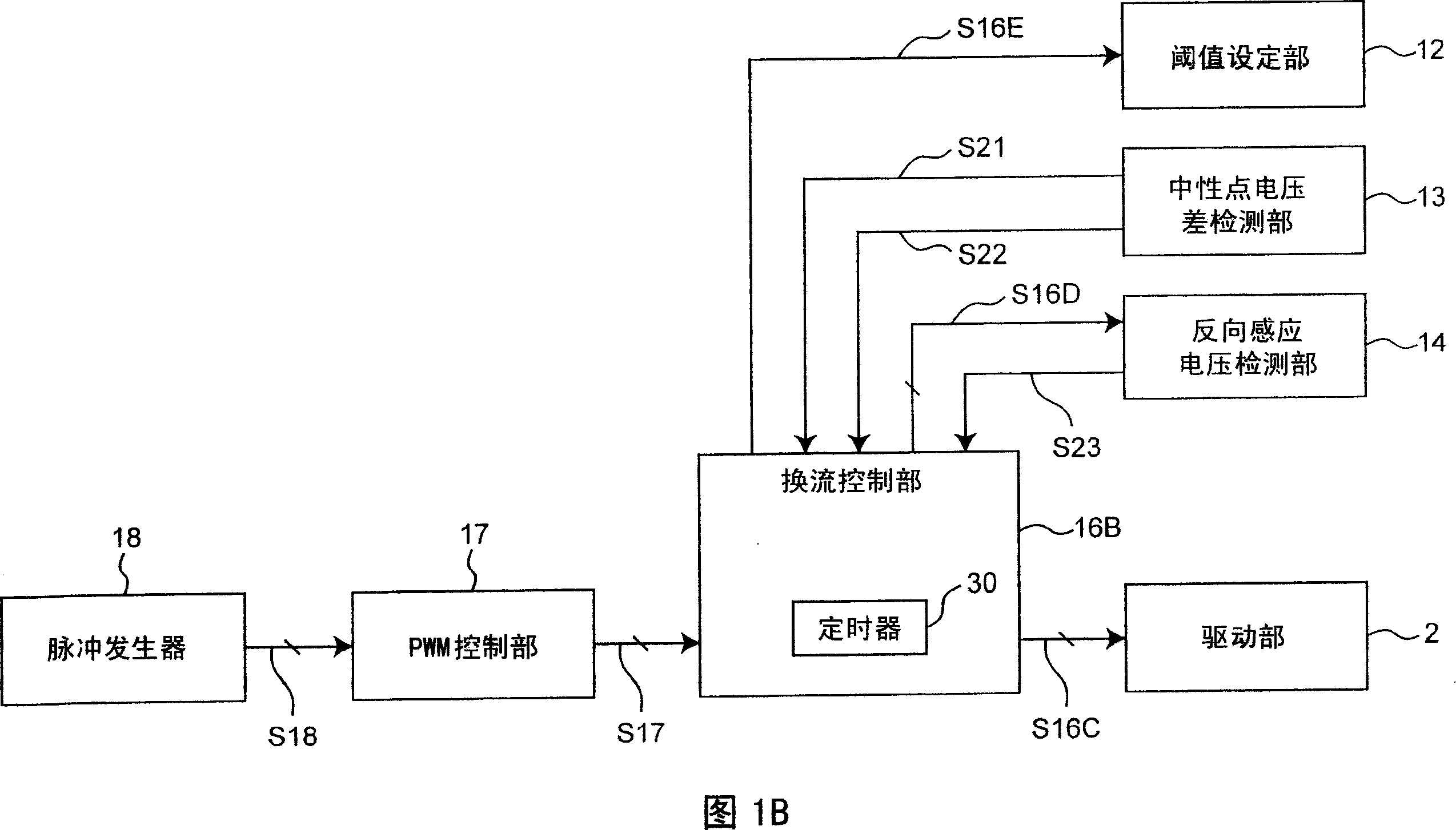
[0066] FIG. 1A shows a circuit configuration in a first embodiment of a motor drive device according to the present invention. In FIG. 1A , the motor drive device includes a motor 1, a drive unit 2, a drive signal generation unit 5, a comparison unit 6, a current detection unit 7, a phase torque command signal generation unit 8, a search command signal generation unit 9, a start command signal A generation unit 10 , an analog neutral point voltage generation unit 11 , a neutral point voltage difference detection unit 13 , and a reverse induced voltage detection unit 14 .

[0067] The motor 1 includes a three-phase stationary stator and a rotor rotating around the stator. In the first embodiment, the three-phase motor 1 is used as the motor, but the present invention can be applied to an N-phase motor by setting N to an integer greater than or equal to 2. The U-phase motor coil LU, V-phase motor coil LV, and W-phase motor coil LW wound in the stator are connected in common thr...

no. 2 approach

[0403] In the first embodiment, the case of two-phase energization has been described. In the second embodiment, the case of three-phase energization will be described focusing on points different from the first embodiment described above. Other configurations, actions, and effects are the same as those of the first embodiment.

[0404] FIG. 20 shows a circuit configuration of a second embodiment of the motor drive device according to the present invention. In FIG. 20 , the motor drive device includes a motor 1, a drive unit 2, a drive signal generation unit 5, a comparison unit 6, a current detection unit 7, a phase torque command signal generation unit 8, a search command signal generation unit 9, a start command signal Generating unit 10 , analog neutral point voltage generating unit 11 , neutral point voltage difference detecting unit 13A, and reverse induced voltage detecting unit 14A.

[0405] The motor 1 includes a three-phase fixed stator and a rotor rotating around ...


PUM


Abstract

A motor driving method is provided. A rotor position is determined based on whether or not a neutral point voltage difference, or a voltage difference between neutral point voltage and pseudo neutral point voltage exceeds a predetermined threshold when an energization phase is sequentially selected and energized. The energization phase for starting a motor is determined based on the result of this determination, and the motor is energized and started according to the determined energization phase. The operation mode is not changed directly from a step for searching the initial position of the rotor to a counter electromotive voltage mode. Instead, a search start mode for supplying appropriate rotational speed to the initial startup of the motor is once established, and then the mode is changed to the counter electromotive voltage mode. Following problems are solved: a problem of the correctness of a peak value of a position detection signal taken in; a problem of proneness to be influenced by a variation in motor characteristics caused by the slightness of differences in detection currents between phases; and a problem that methods of comparing voltage differences determined with respect to each group of measured voltages that occurs at a neutral point of motor windings each time a detection signal is applied to determine a large voltage difference require a reference table and high computing power.

Description

technical field [0001] The present invention relates to a three-phase brushless motor drive technology capable of stably and rapidly starting without a rotor position sensor. Background technique [0002] In the brushless motor, the stator selects an appropriate coil, and flows a current to provide a stable torque to the rotor. Therefore, the electrical relative position of the rotor to the stator is required. In order to know this relative position, various rotor position sensors are used. On the other hand, in terms of reliability, cost increase, and environmental resistance, sensorless drive technology that does not require a rotor position sensor has also been developed. Among such sensorless driving techniques, there is generally known a technique of detecting a rotor position by reading a reverse induced voltage generated in a stator phase coil when the rotor rotates. However, since the reverse induced voltage is not generated when the rotor is stopped, various dete...

Claims


Application Information

Patent Timeline
Patent Type & Authority Applications(China)
IPC IPC(8): H02P6/18H02P6/06H02P6/08H02P6/182H02P6/21
CPCH02P6/182H02P6/205H02P6/22H02P6/21
Inventor 深水新吾山本泰永黑岛伸一
Owner PANASONIC CORP
Why Eureka
Try Eureka