Thermal expansion type ultrahigh-pressure energy conservation device

An energy conversion device and thermal expansion technology, applied in injection devices, liquid injection devices, etc., can solve problems such as high requirements for seals, affecting high-pressure injection, failing to meet sealing requirements, etc.

Inactive Publication Date: 2013-01-30
夏致俊
View PDF4 Cites 0 Cited by
  • Summary
  • Abstract
  • Description
  • Claims
  • Application Information

AI Technical Summary

Problems solved by technology

[0002] In the traditional occasions where high-pressure injection is required, the plunger structure is generally used for high-pressure injection. This structure can realize high-pressure injection, but due to the high injection pressure, the requireme

Method used


Image

  • Thermal expansion type ultrahigh-pressure energy conservation device
  • Thermal expansion type ultrahigh-pressure energy conservation device

Examples


Embodiment 1

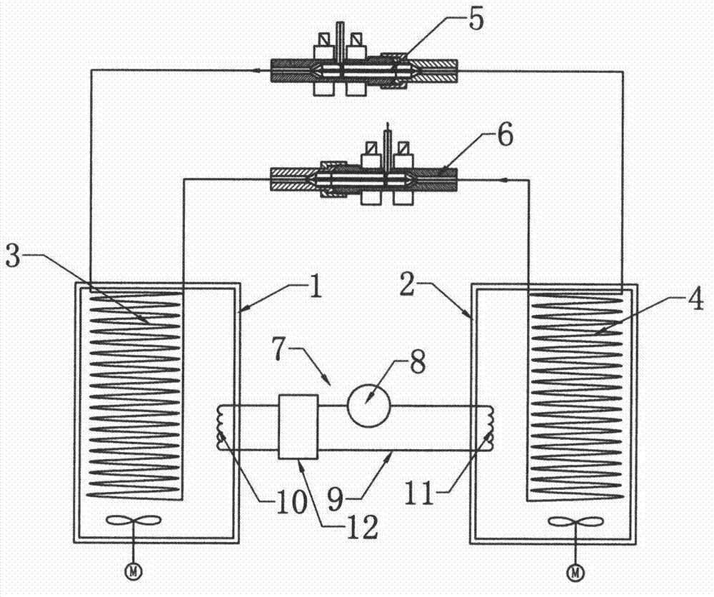
[0015] Such as figure 1 As shown, the thermal expansion type ultra-high pressure energy conversion device of the present invention includes No. 1 cold and heat exchange water tank 1 and No. 2 cold and heat exchange water tank 2, and No. 1 cold and heat exchange pipe 3 and No. Cooling and heat exchange pipe 4; No. 1 cold and heat exchanging pipe 3 and No. 2 cold and heat exchanging pipe 4 are provided with replenishing water switching valve 5 and spray water switching valve 6 respectively connecting the two cold and heat exchanging pipes end to end; water replenishing switching valve 5 and water spray switching valve 6 are set in the opposite direction, so that alternate water spray and alternate water intake can be realized and the liquid medium in the two cold and heat exchange pipes can be alternately switched between cold and heat; A cooling and heating switching device 7 that can switch the liquid medium in the two cold and heat exchanging water tanks between cold and hot,...

Embodiment 2

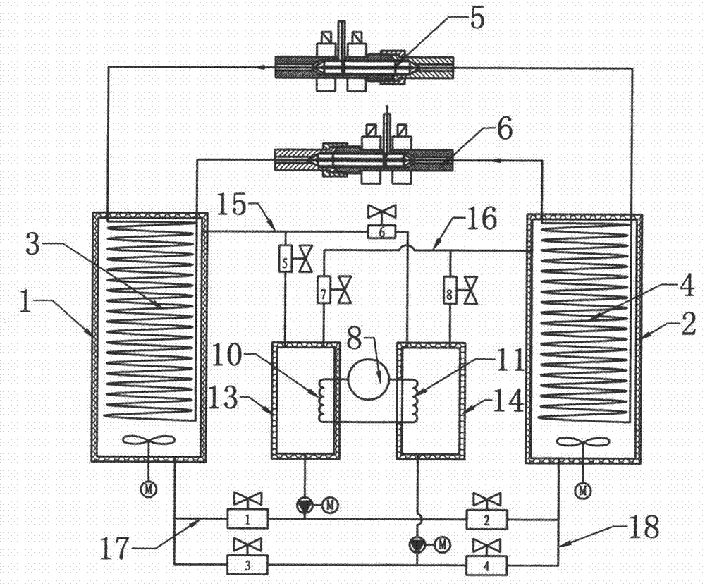
[0018] In this embodiment, the cooling and heating switching device 7 includes a heat pump 8 and a cold and hot medium circulation pipeline 9 connected to the heat pump 8; 11. The evaporator 10 and the condenser 11 are respectively arranged in the hot water tank 13 and the cold water tank 14, and the hot water tank 13 and the cold water tank 14 are respectively connected with the No. 1 cold and heat exchange water tank 1 and the No. 2 cold and heat exchange water tank 2 There are interconnected branches, and a reversing device that can change the flow direction of the medium in the heat pump is arranged on the branch, and the cold and hot media at the cold and heat exchange end can be switched alternately through the reversing device; among them, there are four branches, and they are respectively It is to connect No. 1 water tank 13 and No. 2 water tank 14 in parallel to No. 1 branch 15 on No. 1 cold and heat exchange water tank 1; connect No. 1 water tank 13 and No. 2 water ta...


PUM


Abstract

The invention discloses a thermal expansion type ultrahigh-pressure energy conservation device for implementing high-pressure jet by using volume expansion or shrinkage of a liquid medium. The device comprises a No.1 cold-heat exchange water tank and a No.2 cold-heat exchange water tank, and a No.1 cold-heat exchange pipeline and a No.2 cold-heat exchange pipeline are respectively arranged in the two cold-heat exchange water tanks; a water supply switching valve and a water spray switching valve are arranged between the No.1 cold-heat exchange pipeline and the No.2 cold-heat exchange pipeline, and the two switching valves are arranged in opposite directions to realize alternated water spray and alternated water supply; and a refrigerating and heating switching device is arranged between the two cold-heat exchange water tanks. The device is simple in structure; the high-pressure jet is implemented by using the volume expansion or shrinkage of the liquid medium, so that the energy loss in the conversion process is low, the required energy can be furthest obtained, the liquid medium can be reused, the energy is saved, and pollution to the environment is avoided; and the sealing links are few, the sealing requirement is low, and the sealing effect is good.

Description

technical field [0001] The invention relates to an energy conversion device, in particular to a thermal expansion type ultra-high pressure energy conversion device which utilizes volume expansion or contraction of a liquid medium for high-pressure injection. Background technique [0002] In the traditional occasions where high-pressure injection is required, the plunger structure is generally used for high-pressure injection. This structure can realize high-pressure injection, but due to the high injection pressure, the requirements for sealing are higher, and the requirements for seals are also higher. High, but the existing plunger structure cannot meet the sealing requirements due to the limitation of the seal, thus affecting the effect of high-pressure injection. Contents of the invention [0003] The technical problem to be solved by the present invention is to provide a thermal expansion ultra-high pressure energy conversion device that utilizes volume expansion or c...

Claims


Application Information

Patent Timeline
IPC IPC(8): B05B9/04
Inventor 夏致俊
Owner 夏致俊
Why Eureka
Try Eureka