
Portable screening machine

A screening machine and portable technology, applied in the field of screening machines, can solve the problems of easily damaged screening machine power parts, large size of screening machines, and inability to transport, saving energy costs, ensuring screening efficiency, and maximizing production efficiency.

Active Publication Date: 2013-01-30
KANGFEI AUTOMATION TECH CO LTD
View PDF5 Cites 2 Cited by
  • Summary
  • Abstract
  • Description
  • Claims
  • Application Information

AI Technical Summary

Problems solved by technology

[0002] For the screening machine used to screen solid particles such as soil or sand, in the original design, the feed inlet of the feed hopper only has a screen mesh, and the feed material is 10 inches or longer than 12 inches. , there is a problem when these materials pass through the feed hopper, these materials usually get stuck at the feed opening of the feed hopper, which stops the screening machine and requires manual removal of these oversized screening residues to continue screening The work is more cumbersome, and it is easy to damage the power part of the screening machine
[0003] In the original conventional design, the power of the screening machine is directly driven by a gasoline engine to work on the screening table, and the power components of the screening machine need to be installed together with the base, so the original conventional design of the screening machine is bulky and cannot be transported

Method used


Image

  • Portable screening machine
  • Portable screening machine
  • Portable screening machine

Examples


Embodiment Construction

[0034] The present invention is described in further detail now in conjunction with accompanying drawing. These drawings are all simplified schematic diagrams, which only illustrate the basic structure of the present invention in a schematic manner, so they only show the configurations related to the present invention.

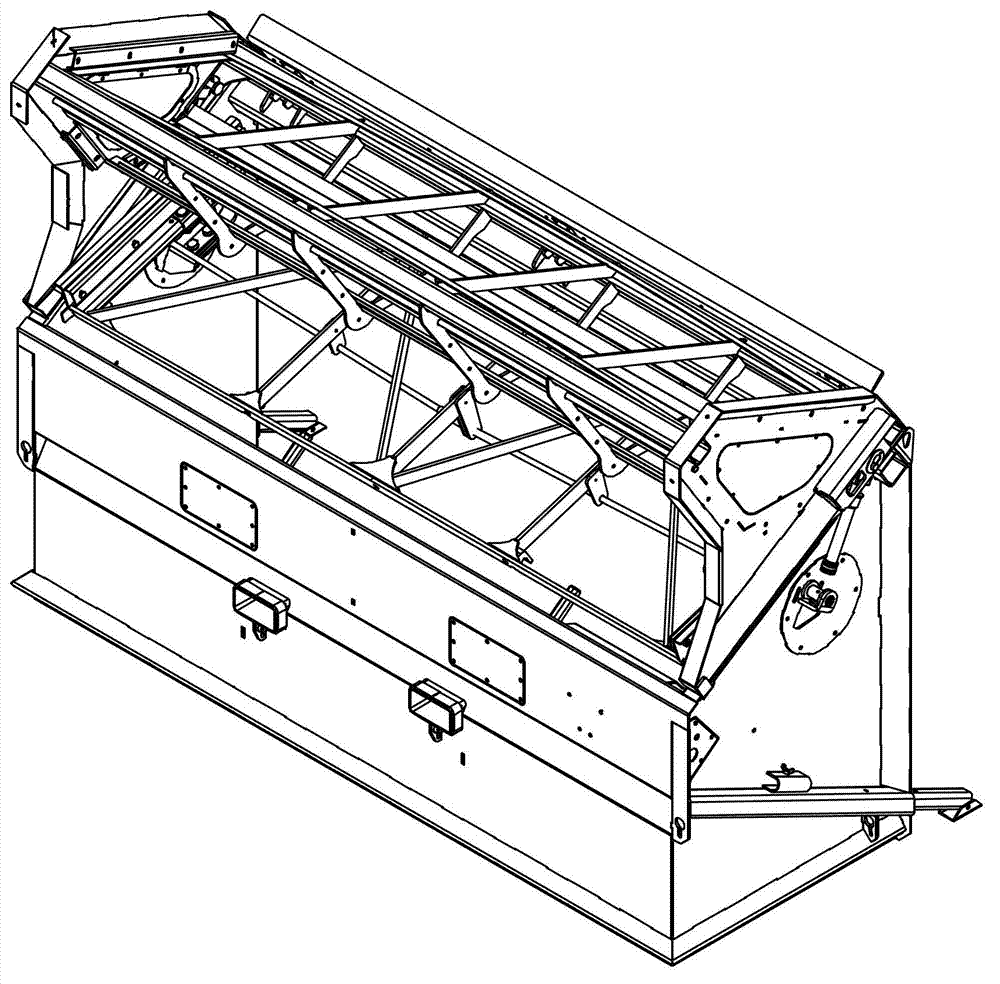
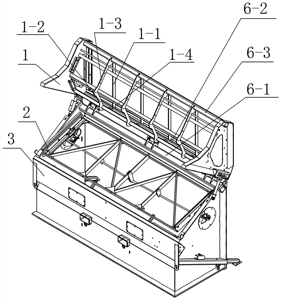
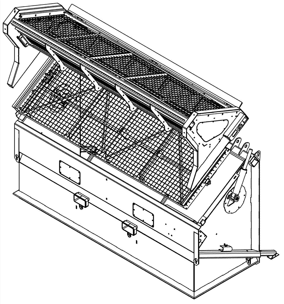
[0035] Such asfigure 1 figure 2 image 3 Figure 4 As shown, a portable screening machine has a base body 3, a screening table 2 is installed on the top of the base body 3, and a feeding screening device 1 is installed above the screening table 2. The feed screening device 1 has left and right installation guide plates, and a first screen support 1-1, a second screen support 1-2, a third screen support 1-3, a fourth Brackets 1-4.

[0036] The first screen support 1-1 is installed on the top of the left and right installation guide plates and is arranged obliquely. The second screen support 1-2 is set at a certain angle relative to the level or horizontal ...


PUM


Abstract

The invention relates to a portable screening machine. The portable screening machine is provided with a supplied material screening device, wherein the supplied material screening device is provided with a left mounting guide plate and a right mounting guide plate; a first screen bracket is obliquely mounted at the tops of the left mounting guide plate and the right mounting guide plate; a second screen bracket and a screening table form a certain angle relative to a horizontal direction or in the horizontal direction; a third screen bracket and the screening table form a certain angle relative to a perpendicular direction or in the perpendicular direction; a fourth bracket is positioned between opposite connecting ends of the first screen bracket and the second screen bracket; a first screen can be mounted on the first screen bracket; a second screen can be mounted on the second screen bracket; a third screen can be mounted on the third screen bracket; screen holes of the first screen are larger than those of the second screen; and screen holes of the second screen are larger than those of the third screen. The portable screening machine can be used for mounting screens with different sizes to prevent ultra-large materials from entering the screening table, so that the damage of the screening machine can be alleviated.

Description

technical field [0001] The invention relates to the technical field of screening machines, in particular to a portable screening machine for screening solid particles such as soil or sand. Background technique [0002] For the screening machine used to screen solid particles such as soil or sand, in the original design, the feed inlet of the feed hopper only has a screen mesh, and the feed material is 10 inches or longer than 12 inches. , there is a problem when these materials pass through the feed hopper, these materials usually get stuck at the feed opening of the feed hopper, which stops the screening machine and requires manual removal of these oversized screening residues to continue screening The work is more cumbersome, and it is easy to damage the power part of the screening machine. [0003] In the original conventional design, the power of the screening machine is directly driven by a gasoline engine to work on the screening table, and the power components of the...

Claims


Application Information

Patent Timeline
Patent Type & Authority Applications(China)
IPC IPC(8): B07B1/28B07B1/42B07B1/46
Inventor 布拉德·可拉可·侯雷姆
Owner KANGFEI AUTOMATION TECH CO LTD
Learn More