Stamping device for thin plate

A thin plate stamping and lifting plate technology, applied in metal processing equipment, forming tools, manufacturing tools, etc., can solve problems such as inconvenience, cumbersome operation, and complex structure

Inactive Publication Date: 2013-01-30
CHANGZHOU LIWEI KNIFE
View PDF10 Cites 12 Cited by
  • Summary
  • Abstract
  • Description
  • Claims
  • Application Information

AI Technical Summary

Problems solved by technology

[0002] The current thin plate stamping device has a complex structure and cumbersome operation, and the stamping of the thin plate is not accura

Method used


Image

  • Stamping device for thin plate
  • Stamping device for thin plate
  • Stamping device for thin plate

Examples


Embodiment Construction

[0014] The present invention will be further described below in conjunction with the accompanying drawings and specific embodiments.

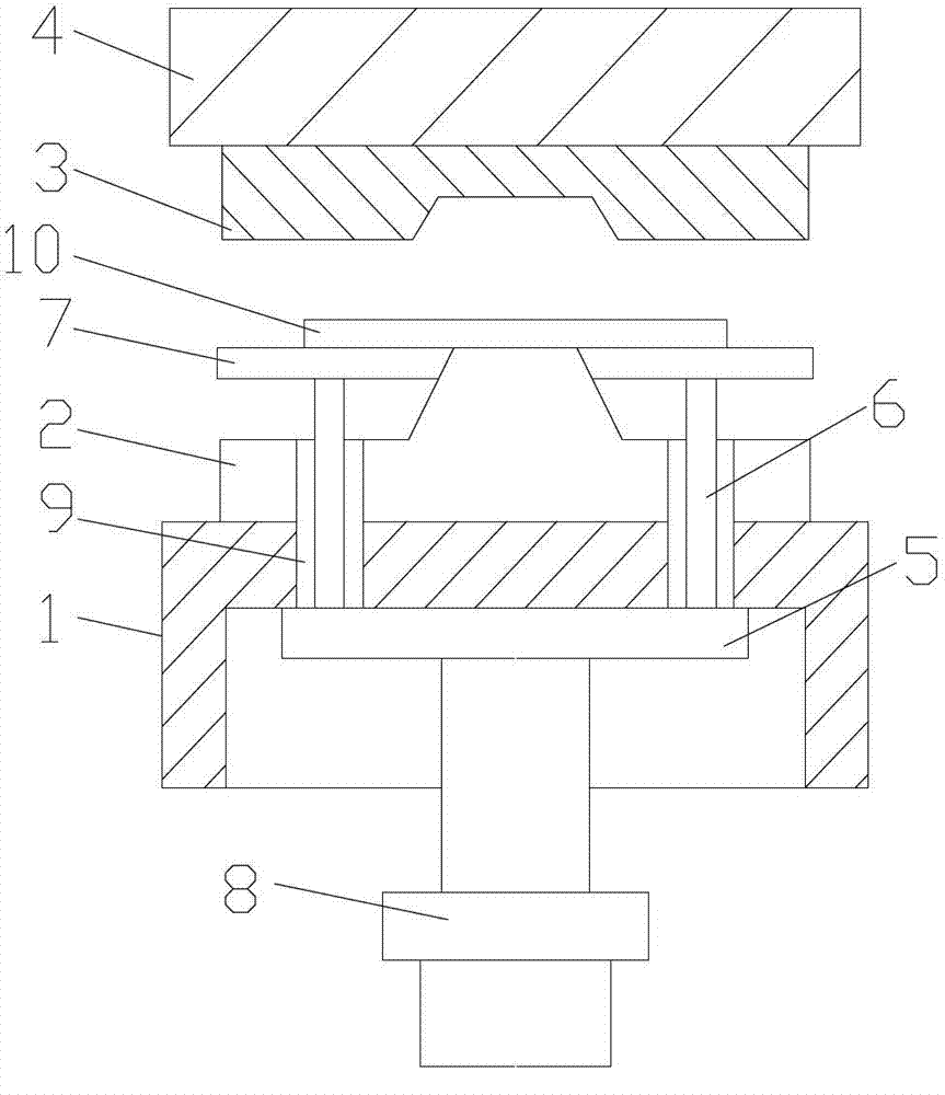
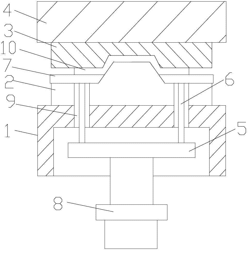
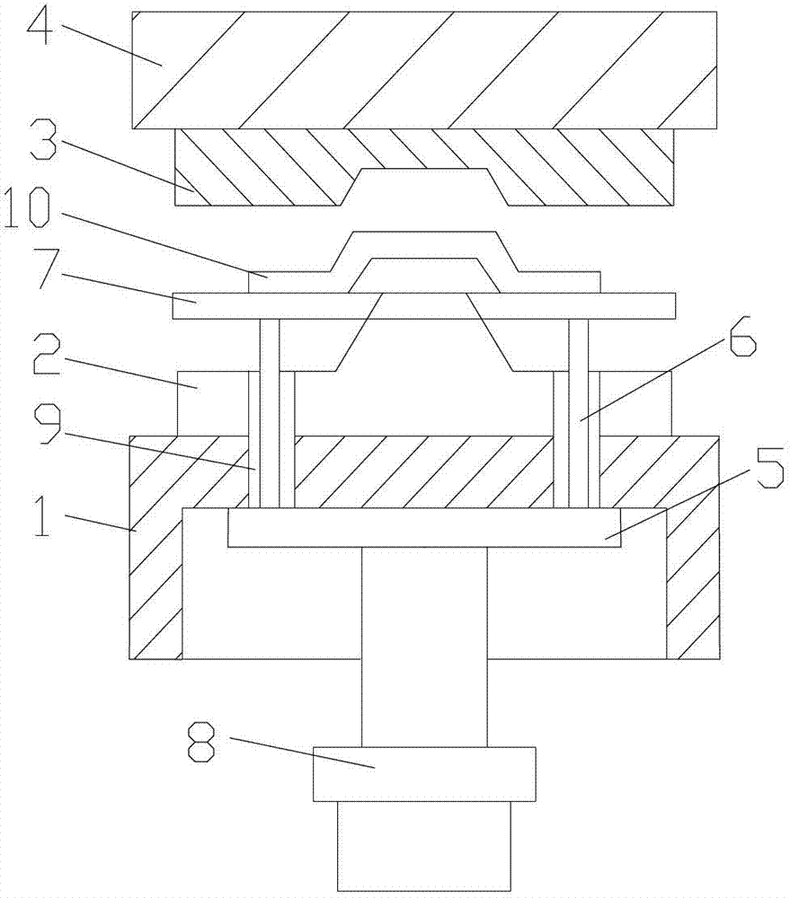
[0015] see figure 1 , 2 , 3. Thin plate stamping device, the stamping hydraulic press includes a workbench 1, a lower punch 2 fixedly arranged on the upper end surface of the workbench 1, and an upper die 3 located above the lower punch 2 and cooperating with the lower punch 2. The die 3 is fixedly arranged on the movable block 4 which can reciprocate up and down, and a lifting plate 5 is arranged under the workbench 1. The upper end surface of the lifting plate 5 is fixedly provided with four guide pins 6, and the upper ends of the guide pins 6 pass through Workbench 1, lower punch 2 is exposed above the lower punch, and the guide rod of the lower punch is exposed. A workpiece 10 is fixedly placed on a flat plate 7, and a punch for the lower punch is provided in the middle of the flat plate 7. Pass through the relief hole, and be arranged on...


PUM


Abstract

The invention relates to a stamping device for a thin plate for processing the thin plate. A hydraulic stamping press comprises an operation platform, a lower raised mould and an upper concave mould, wherein the lower raised mould is fixedly arranged on an upper end face of the operation platform; the upper concave mould is located above the lower raised mould and is matched with the lower raised mould; the upper concave mould is fixedly arranged on a moving block which is capable of vertically reciprocating; a lifting plate is arranged under the operation platform; at least two guiding jacking rods are fixedly arranged on the upper end face of the lifting plate; the upper ends of the guiding jacking rods pass through the operation platform and the lower ends are exposed above the lower raised mould; a workpiece loading flat plate is fixedly arranged on the guiding jacking rods which are exposed out of the lower raised mould; the middle part of the workpiece loading flat plate is provided with an avoiding hole and a driving cylinder; a raised mould on the lower raised mould passes through the avoiding hole; the driving cylinder is arranged under the operation platform and is used for driving the lifting plate to vertically reciprocate; and an upper end of a stretching rod of the driving cylinder is fixedly arranged with the lower end face of the lifting plate. The stamping device has the advantages of simple structure, convenience in operation, easiness in mounting and dismounting, positioning accuracy, high stamping quality and small occupied area.

Description

technical field [0001] The invention relates to stamping equipment in the technical field of mechanical processing equipment, in particular to a thin plate stamping device for processing thin plates. Background technique [0002] The current thin plate stamping device has a complex structure and cumbersome operation, and the stamping of the thin plate is not accurate enough. It is inconvenient to install and disassemble the mold, and it takes a long time to replace a set of molds, which affects work efficiency. Contents of the invention [0003] In view of the above technical problems, the present invention provides a thin plate stamping device, which has a simple structure, convenient operation, easy installation and disassembly, accurate positioning, and high stamping quality. [0004] Realize the technical scheme of the present invention as follows: [0005] Thin plate stamping device, the stamping hydraulic press includes a worktable, a lower punch fixedly arranged on...

Claims


Application Information

Patent Timeline
IPC IPC(8): B21D22/02B21D45/02B21D37/12
Inventor 周建国夏利荣
Owner CHANGZHOU LIWEI KNIFE
Why Eureka
Try Eureka