Flaring mechanism for pipe expander

A tube expander and flaring tube technology, applied in the field of flaring mechanism, can solve the problems of increasing operation difficulty and operation time, high assembly process installation, easy to produce defective products, etc., so as to reduce operation time and operation difficulty and save space , The effect of reducing the defective rate

Inactive Publication Date: 2013-01-30
OMS MASCH CO LTD
View PDF7 Cites 8 Cited by
  • Summary
  • Abstract
  • Description
  • Claims
  • Application Information

AI Technical Summary

Problems solved by technology

This structure has the following disadvantages: 1. The flaring mechanism is located above the guide rail and needs to be lifted and lowered by the lifting frame. Not only is the structure complex and bulky, but also the connection between the flare mounting plate and the guide rail is accurate, and the assembly process is high; 2. Due to the separate processes of tube expansion and expansion, two processes of aligning copper tubes are required, which increases the difficulty and time of operation, and is prone to defective products

Method used


Image

  • Flaring mechanism for pipe expander
  • Flaring mechanism for pipe expander
  • Flaring mechanism for pipe expander

Examples


Embodiment Construction

[0022] Below in conjunction with accompanying drawing, the present invention is described in detail:

[0023] Such as figure 1 , figure 2 , image 3 and Figure 4 as shown,

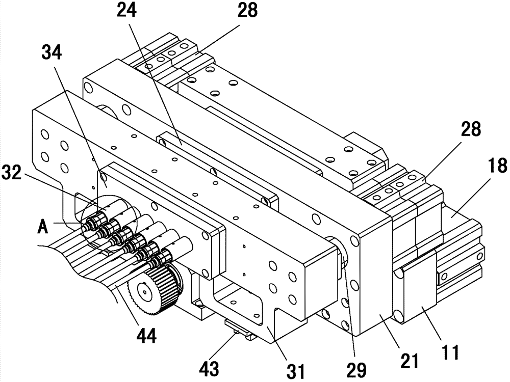
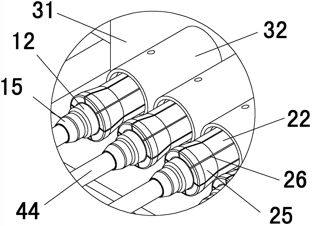
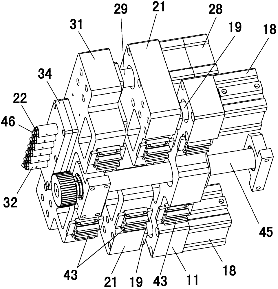
[0024] The invention is applied in a tube expander and is located on a guide rail close to one end of a U-shaped tube fixing bracket.

[0025] The present invention includes a flared mounting plate 11 connected to the guide rail and a flared pipe 12 installed on the flared mounting plate 11, the flared mounting plate 11 has a first through hole 13, and the flared mounting plate 11 is installed on the front side The first fixed plate 14 is arranged to block the first through hole 13, and several flared tube mounting holes are provided on the first fixed plate 14, and the flared tube 12 is installed in the flared tube mounting hole, and the flared tube 12 front end Flaring head 15 is provided on the outside. The expansion rod 44 of the tube expander passes through the first through hole 13 from the b...


PUM


Abstract

The invention discloses a flaring mechanism for a pipe expander. The flaring mechanism comprises a flaring installing plate connected with a guide rail of the pipe expander and a flaring pipe arranged on the flaring installing plate, wherein a plurality of flaring pipe installing holes are formed on the flaring installing plate, the flaring pipe is arranged in the flaring pipe installing holes, the front end of the flaring pipe is externally provided with a cone-shaped flaring head, an expanding rod of the pipe expander is covered in the flaring pipe from the back, and the expanding rod can axially move relative to the flaring pipe; and the flaring pipe is externally covered with a clamping device, and the clamping device can axially move relative to the flaring pipe. The flaring mechanism is simple in structure, convenient to install, and space-saving since not needing to be lifted up and down; when a pipe expanding working procedure is carried out by the pipe expander, an opening of a U-shaped pipe leans against the front end face of the flaring pipe, the opening of the U-shaped pipe is clamped by the clamp device, and the expanding rod extends out of the flaring pipe to expand the pipe, so that the quality of finished products can be guaranteed; and after the pipe is expanded, the flaring can be carried out without needing to withdraw the expanding rod, so that the operation time and difficulty for realigning the pipe opening can be reduced, and the defective rate can be reduced as well.

Description

(1) Technical field: [0001] The invention relates to a flaring mechanism of a tube expander, in particular to a flaring mechanism of a horizontal tube expander. (two) background technology: [0002] The existing tube expander includes a tube expansion part and a flaring part. The tube expansion part includes a U-shaped tube fixing bracket, a guide rail, and a copper tube fixing part is arranged on the U-shaped tube fixing bracket to fix the U-shaped end of the U-shaped tube. The expansion rod is installed on the guide rail, and the expansion rod is pushed by the expansion rod driving mechanism to move along the guide rail. The expansion rod enters the copper tube from the U-shaped tube nozzle to realize tube expansion; its flared part includes a mounting plate, and the mounting plate is equipped with a driving mechanism And the expansion head, the mounting plate is installed on the lifting frame above the movable guide rail of the expansion rod. After the U-shaped tube expan...

Claims


Application Information

Patent Timeline
IPC IPC(8): B21D41/02
Inventor 龙晓斌肖世文潘国峰
Owner OMS MASCH CO LTD
Why Eureka
Try Eureka