Special fixture for machining groove on small pressure bar

A special fixture and small push rod technology, applied in the direction of manufacturing tools, metal processing equipment, metal processing machinery parts, etc., can solve the problems of high precision requirements, inability to locate small push rods, etc., to achieve the effect of convenient operation and simple structure

Inactive Publication Date: 2013-01-30
SUZHOU RIHE SEWING EQUIP
View PDF6 Cites 1 Cited by
  • Summary
  • Abstract
  • Description
  • Claims
  • Application Information

AI Technical Summary

Problems solved by technology

[0004] Small push rod parts in sewing machine parts, see attached Figure 1-3, it mainly includes the rod part and the end of the rod, wherein the end of the rod has a The through hole, the horizontal left and right direction refers to the direction perpendicular to the length of the rod. There is a groove in the middle of the end of the rod. Since the groove needs to be matched with other parts during installation, the accuracy requirements are relatively high. High, so generally the groove needs to be machined after casting, so as to ensure its cooperating installation with subsequent parts. However, the existing fixture cannot locate the small plunger during machining, and a special fixture is needed to realize its positioning. Machining of the finished groove

Method used


Image

  • Special fixture for machining groove on small pressure bar
  • Special fixture for machining groove on small pressure bar
  • Special fixture for machining groove on small pressure bar

Examples


Embodiment Construction

[0020] The structure of the present invention will be further described below in conjunction with the accompanying drawings.

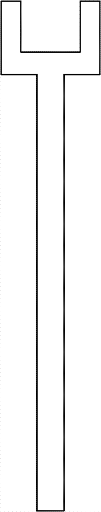
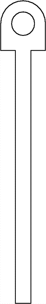
[0021] see Figure 4-7 As shown, a special fixture for the processing of a small plunger groove, including a fixture base 1, the fixture also includes a first fixed block 2 and a second fixed block 3 fixedly arranged on the fixture base 1, fixedly connected to the fixture base 1 The V-shaped block 8 on the top, the first fixed block 2 and the second fixed block 3 are provided with threaded holes penetrating in the horizontal direction along the left and right directions. Rod 4 and the second positioning rod 5, the first positioning rod 4 passes one end of the first fixed block 2 and the second positioning rod 5 passes through one end of the second fixed block 3. There is a protrusion, the protrusion The diameter of the part is smaller than the inner diameter of the above-mentioned threaded hole. The fixture also includes a detachable connection wi...


PUM


Abstract

The invention discloses a special fixture for machining a groove on a small pressure bar. The ends of the pressure bar are positioned by a first positioning bar and a second positioning bar of the fixture, and a shank of the pressure bar is positioned by a V-shaped block and a pressure plate of the fixture. The special fixture is simple in structure and convenient to operate. The small pressure bar is effectively positioned and clamped by the special fixture so as to facilitate machining.

Description

[0001] technical field [0002] The invention relates to a special fixture for processing small plunger grooves. [0003] Background technique [0004] For the small pressing rod parts in the sewing machine parts, see the attached Figure 1-3 As shown, it mainly includes the rod part and the end part of the rod, wherein the end part of the rod has a through hole penetrating along the horizontal left and right direction. The horizontal direction refers to the direction extending perpendicular to the length of the rod part. There is a groove in the middle, because the groove needs to cooperate with other parts during installation, and its precision requirements are high, so the groove needs to be machined after casting to ensure its matching with subsequent parts. Existing fixtures can't locate the small plunger during processing, and special fixtures are needed to realize its positioning and complete the processing of the groove. [0005] Contents of the invention [00...

Claims


Application Information

Patent Timeline
Patent Type & Authority Applications(China)
IPC IPC(8): B23Q3/06
Inventor 孙君
Owner SUZHOU RIHE SEWING EQUIP
Why Eureka
Try Eureka