Mold capable of realizing delayed ejection and accelerated ejection simultaneously

A technology of accelerating top and mold, applied in the field of mold structure combining slow top and accelerating top, and ejecting structure, it can solve the problems of complicated interaction and connection, unable to realize slow top, complicated action process, etc., and achieve low processing and manufacturing cost. , improve the accuracy and increase the effect of production efficiency

Active Publication Date: 2013-01-30
佛山市顺德区容声塑胶有限公司
View PDF5 Cites 2 Cited by
  • Summary
  • Abstract
  • Description
  • Claims
  • Application Information

AI Technical Summary

Problems solved by technology

In actual production operation, in order to prevent the product from whitening and the product from the flat top of the forming ribs for the large volume and complex module products with many internal ribs, it is necessary to set up two structures of slow top and accelerated top. Ordinary secondary ejection structure requires two sets of push-out plates and push-out fixing plates, resulting in problems such as complex ejection structure, complicated action process, reduced work efficiency, and high cost.
[0004] In addition, the existing single accelerated ejector structure in the mold industry itself is relatively complicated. The specific structure is: two sets of ejector plates are made on the mold, and one set of ejector plates is accelerated by using the leverage principle when the mold is ejected; and the mold industry is now Some acceleration top structures cannot realize slow top, which greatly reduces the flexibility of the mold to face various module operations, and at the same time makes the interaction and connection in the structure more complicated

Method used


Image

  • Mold capable of realizing delayed ejection and accelerated ejection simultaneously
  • Mold capable of realizing delayed ejection and accelerated ejection simultaneously
  • Mold capable of realizing delayed ejection and accelerated ejection simultaneously

Examples


Embodiment 2

[0032] The structure and principle of this embodiment are basically the same as that of Embodiment 1, the difference is that:

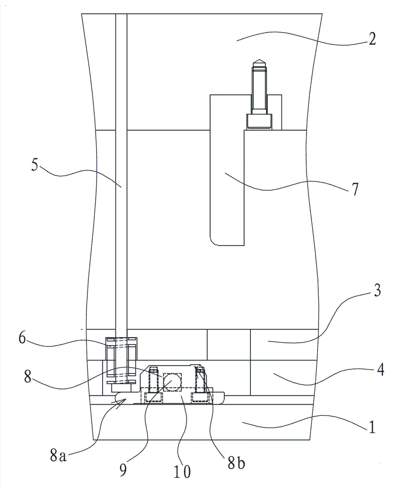
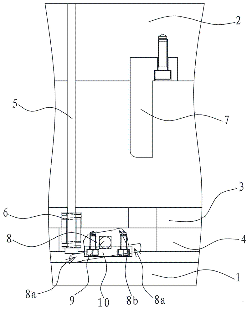
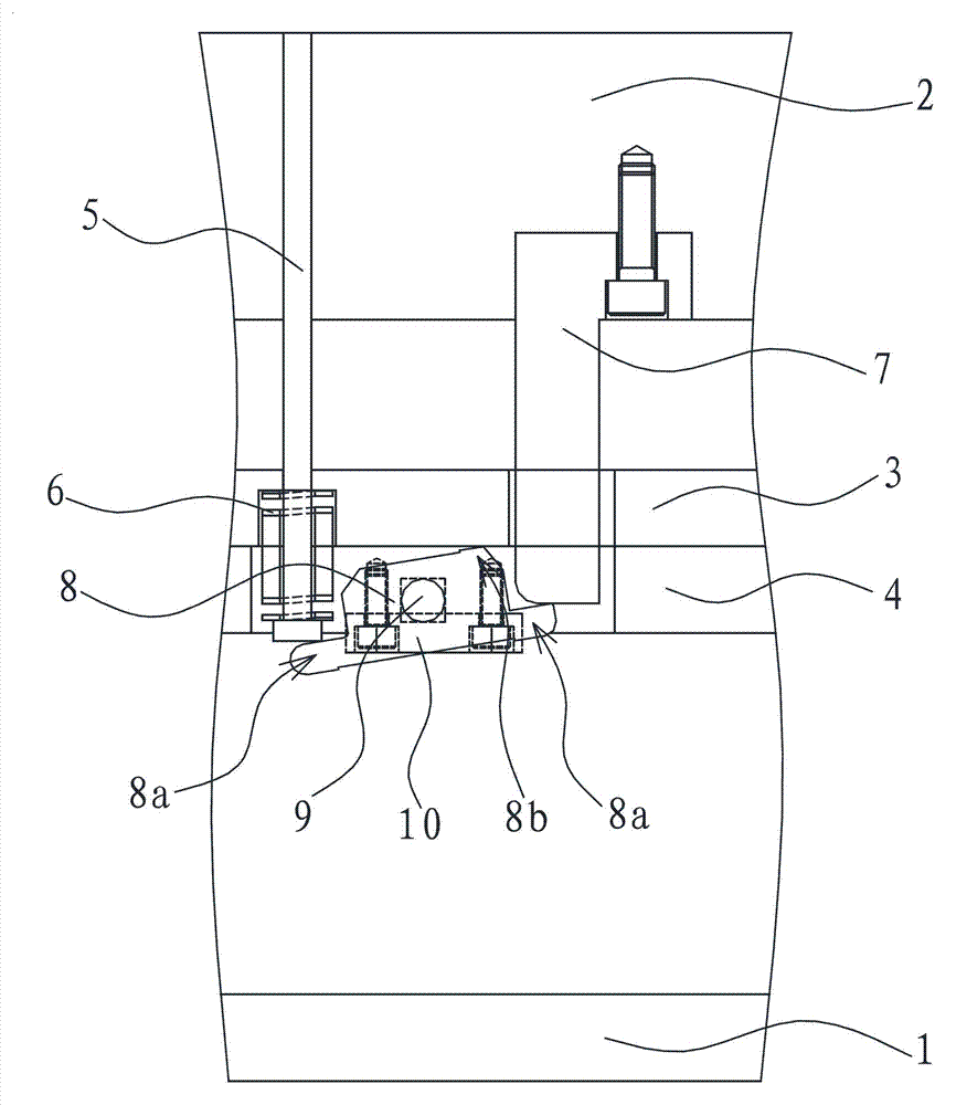
[0033] The acceleration gear lever is integrally fixed on one side swing end 8a of the acceleration top block 8, and the acceleration gear lever extends vertically upward. When the acceleration top block 8 abuts against the initial position of the movable mold fixed plate 1, the top of the acceleration stop bar and the movable template 2 are separated by a certain space distance, and because the area of ​​the movable template 2 is relatively large, the acceleration top block 8 rises to When in a proper position, the acceleration stop lever on one side of the swing end 8a can be in contact with the bottom surface of the movable template 2, and then the acceleration top action can be realized through the seesaw principle.


PUM


Abstract

The invention provides a mold capable of realizing delayed ejection and accelerated ejection simultaneously, and solves the problems that the conventional ejection structure is complicated, a matching effect is poor, working efficiency is reduced, and the like because only delayed ejection or accelerated ejection can be realized independently. The mold capable of realizing delayed ejection and accelerated ejection simultaneously comprises a movable mold fixing plate positioned on the bottom side and a movable mold plate positioned on the upper side, wherein an ejector plate capable of vertically lifting is arranged in a space between the movable mold fixing plate and the movable mold plate; an ejector rod slidably penetrates through the ejector plate along the vertical direction; the ejector plate is hinged with an accelerated ejector block; the swing end of one side of the accelerated ejector block is pressed against and in contact with the bottom of the ejector rod; and an accelerated blocking rod is arranged between the swing end of the other side of the accelerated ejector block and the movable mold plate. The accuracy of an ejection effect is perfected, a discharging effect, success rate and working efficiency are improved, and the mold is flexibly operated.

Description

technical field [0001] The invention belongs to the technical field of injection molds, and relates to an ejection structure, in particular to a mold structure combining a slow ejector and an accelerated ejector. Background technique [0002] Molds are various molds and tools used in industrial production for injection molding, blow molding, extrusion, die-casting or forging forming, smelting, stamping, stretching and other methods to obtain the required products. In short, a mold is a tool used to shape an object. This tool is composed of various parts, and different molds are composed of different parts. It mainly realizes the processing of the shape of the article through the change of the physical state of the formed material. [0003] During the unloading process of the molded parts, it is usually realized by the action of the ejector structure. In actual production operation, in order to prevent the product from whitening and the product from the flat top of the form...

Claims


Application Information

Patent Timeline
Patent Type & Authority Applications(China)
IPC IPC(8): B29C45/40
Inventor 赵利宁盛希龙
Owner 佛山市顺德区容声塑胶有限公司
Why Eureka
Try Eureka