Electric generation system capable of utilizing potential energy to generate electric energy

A power generation system and potential energy technology, which is applied in the direction of traction, engine, and electric vehicles driven by engines, can solve problems such as not being used well, and achieve huge social, economic and environmental benefits, easier manufacturing and installation, and fuel saving.

Inactive Publication Date: 2013-01-30
陈冠卿
View PDF6 Cites 0 Cited by
  • Summary
  • Abstract
  • Description
  • Claims
  • Application Information

AI Technical Summary

Problems solved by technology

As it stands, this potential energy is not well and efficiently utilized in vehicles!

Method used


Image

  • Electric generation system capable of utilizing potential energy to generate electric energy
  • Electric generation system capable of utilizing potential energy to generate electric energy

Examples


Embodiment Construction

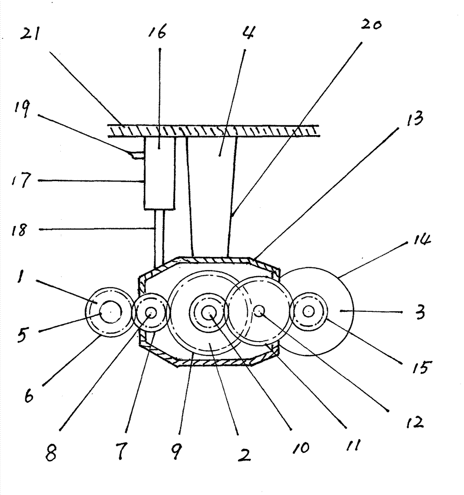
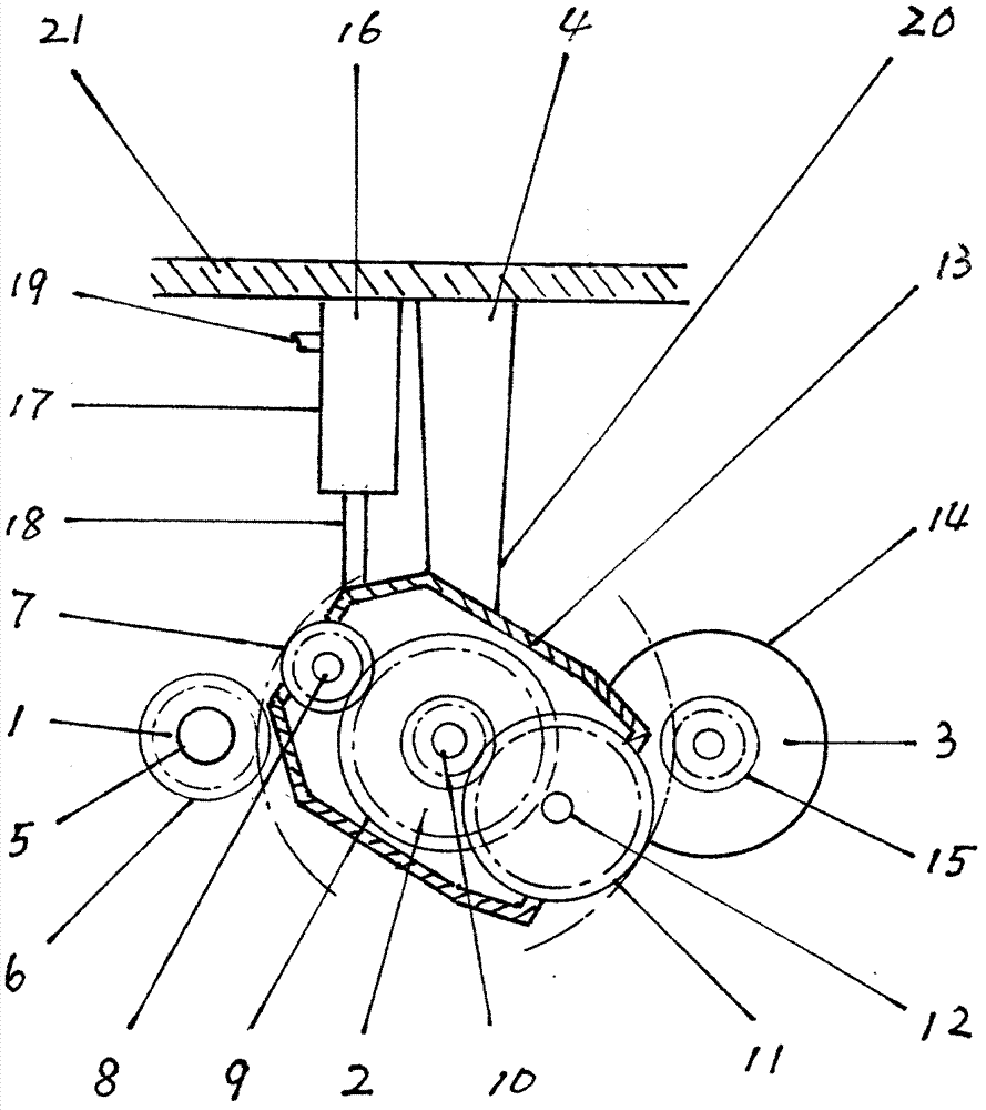
[0012] exist figure 1 Among them, 1 is the mining device, 2 is the transmission device, 3 is the power generation device, and 4 is the mining auxiliary device. The mining device 1 is composed of a transmission shaft 5 and a mining wheel 6 . Transmission shaft 5 is the power transmission shaft on the vehicle. Mining pulley 6 is a gear, also can be a sheave when needed, is made of metal. The driving wheel 6 is installed and fixed on the power transmission shaft 5 . Transmission device 2 is made of transmission wheel 7, transmission wheel shaft 8, transmission main wheel 9, transmission main wheel shaft 10, transmission auxiliary wheel 11, transmission auxiliary wheel shaft 12 and transmission device casing 13. The two ends of the transmission wheel shaft 8 and the transmission auxiliary wheel shaft 12 are installed and fixed on the inner wall of the transmission case 13 respectively. Drive wheel 7 is installed on the drive wheel shaft 8, and drive wheel 7 can rotate around d...


PUM


Abstract

An electric generation system capable of utilizing potential energy to generate electric energy can be applied to vehicles, electric and hydrogen new energy vehicles, hybrid vehicles, tractors and wheel type military vehicles and belongs to the field of automobile generation devices. The electric generation system comprises a driving device, a transmission device, a generating device and an auxiliary driving device. A transmission wheel and an auxiliary transmission wheel on the transmission device can be meshed with a driving wheel on the driving device and a generator wheel on the generating device. Via a control system on a vehicle, a clutch of the auxiliary driving device enables the transmission device and the driving device to be separated or combined with the generating device. The electric generation system is capable of utilizing potential energy during traveling of the vehicle to generate electric energy which is supplied to vehicle-mounted electrical equipment or used as a motive power to drive the vehicle to run when needed. The electric generation system capable of utilizing potential energy to generate electric energy is capable of saving fuel oil and energy and environment-friendly, and has great social economic benefit.

Description

Technical field [0001] The invention belongs to the field of vehicle power generation equipment. Background technique [0002] When the vehicle is driving on the road, due to the continuous change of the terrain, the road will have ups and downs. When the vehicle is driving on a downhill road, due to the mass, speed, friction between the wheels and the ground, and the gravitational force of the earth, a very powerful dive force that automatically moves forward will be generated, which is potential energy. In addition, the vehicle will also produce strong inertial motion when driving on a flat road, especially at high speed. This potential energy is actually an endless source of energy. As it stands, this potential energy is not well and efficiently utilized in vehicles! Contents of the invention [0003] The purpose of the present invention is to overcome the deficiencies of the prior art and provide a power generation system that can utilize potential energy to generat...

Claims


Application Information

Patent Timeline
Patent Type & Authority Applications(China)
IPC IPC(8): B60L11/14F03G3/08B60L50/16
CPCY02T10/7077Y02T10/7072
Inventor 陈冠卿陈洪涛陈洪波
Owner 陈冠卿
Why Eureka
Try Eureka