Automobile roof rack

A technology for luggage racks and automobiles, which is applied to vehicle parts, additional accessories, transportation and packaging, etc., can solve the problems of reduced leg strength, over-prioritized functions, and reduced strength, and achieves the effect of improving appearance, strengthening strength, and improving appearance.

Inactive Publication Date: 2013-01-30
RIKENSEIKO
View PDF9 Cites 1 Cited by
  • Summary
  • Abstract
  • Description
  • Claims
  • Application Information

AI Technical Summary

Problems solved by technology

[0003] At this time, since the engaging claws are protruded from the ends of the leg covers or the leg caps, and the engaging holes serving as vent holes capable of engaging the engaging claws are provided at the ends of the corresponding legs, the ends of the legs In addition, in recent years, in order to reduce the weight, reinforcement ribs are provided in the axial and transverse directions of the legs. Since a large space is formed between the reinforcement ribs, there is a problem that the strength of the entire leg is reduced.
[0004] In addition, since the surface of the roof rack is formed as a uniform smooth surface, a pair of legs are assembled at both ends, and the entire surface of the legs is covered with a leg cover or a leg cap, so the appearance after assembly is different from that of the luggage. A pair of leg covers or leg caps are exposed at both ends of the frame, some of which are too functional and lack aesthetics

Method used


Image

  • Automobile roof rack
  • Automobile roof rack
  • Automobile roof rack

Examples


Embodiment Construction

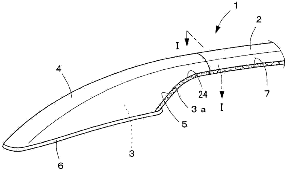
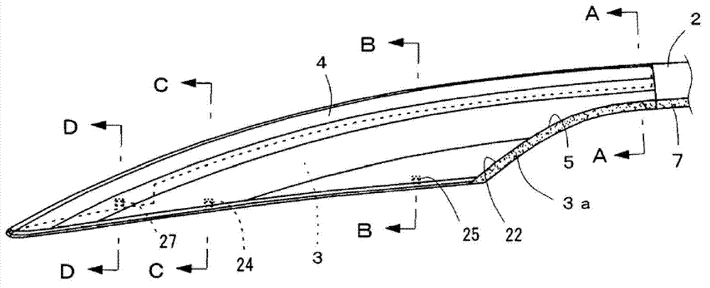
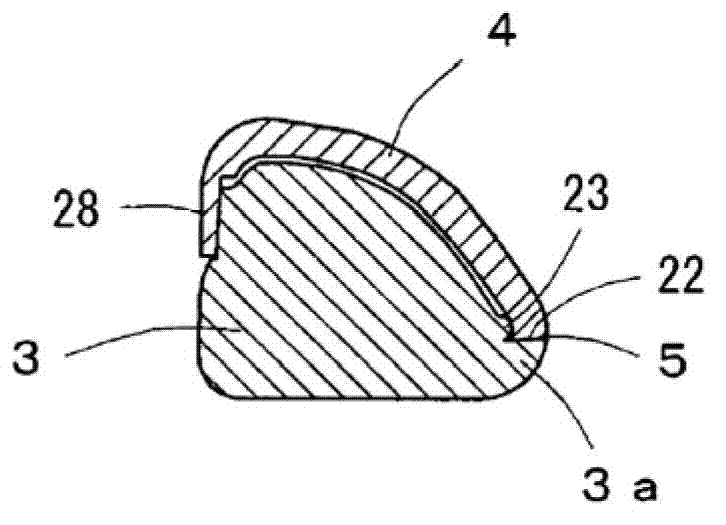
[0072] Hereinafter, the present invention will be described with reference to the illustrated embodiments. Figure 1 to Figure 1 In 7, 1 is a roof rack for automobiles, which is covered by a pair of left and right roof racks 2 made of metal pipes, and synthetic resin legs 3 installed at the front and rear ends of the roof rack 2. The leg part 3 rear part except the synthetic resin leg cover 4 of the upper side peripheral surface of the decorative part mentioned later is constituted, and the boundary part between the lower edge part of the outside rear of the leg part cover 4 and the above-mentioned decorative part is formed to cover it. Divide the curved line-like dividing line (see 切り)5. In the figure, 6 is a sealing gasket assembled under the leg 3 .

[0073] The above-mentioned roof rack 2 is formed by extruding or pulling out aluminum, bending it in a three-dimensional direction, forming its cross-sectional shape into a trapezoidal or triangular shape as shown in FIG. 17 ...


PUM


Abstract

The invention provides an automobile roof rack to conveniently install a leg cover and a leg and to improve post-installation appearance of a roof rack and the leg and the leg cover and the leg as well as enhance the strength of the leg. A connecting shaft part (8) of the leg (3) is inserted and fixed at two ends of the roof rack (2). A plurality of clamping groove (17)-(19) are formed at two sides of the leg (3). The leg cover (4) enables a pluraligy of clamping claws (24)-(37) which can be clamped in the clamping groove (17)-(19) to protruded on an inner surface is disposed. The leg cover (4) covers the leg (3). A decorative part (3a) is disposed protruding sidewards on at least one side peripheral face of a rear part of the leg (3). A lower end of the leg cover (4) can be recived in the decorative part (3a) in a clamping manner. The decorative part (3a) shows itself towards below the leg cover (4).

Description

technical field [0001] The invention relates to a roof rack for automobiles, which can easily install the leg cover and the leg, strengthen the strength of the leg, and improve the relationship between the roof rack and the leg, and the leg cover and the leg. Appearance after installation. Background technique [0002] A roof rack for an automobile generally consists of a tubular roof rack bent in three-dimensional directions, a pair of strong front and rear legs mounted on both ends of the roof rack, a leg cover covering the legs, or The leg cap is formed by pressing or inserting the leg into the roof rack, and bonding or screwing these, and snapping and assembling the leg cover or the leg cap on the surface of the leg (for example, refer to the patent document 1 and 2). [0003] At this time, since the engaging claws are protruded from the ends of the leg covers or the leg caps, and the engaging holes serving as vent holes capable of engaging the engaging claws are provi...

Claims


Application Information

Patent Timeline
Patent Type & Authority Applications(China)
IPC IPC(8): B60R9/04
Inventor 庭山浩
Owner RIKENSEIKO
Why Eureka
Try Eureka