Differential pressure feedback type flow divider valve

A feedback type, diverter valve technology, applied in the direction of fluid pressure actuators, servo motor components, mechanical equipment, etc., can solve the problem that diverter valves cannot realize the lifting movement of equal-thrust single-acting hydraulic cylinders, and are not suitable for walking agricultural machines, Problems such as the bulky size of the diverter valve, to achieve the effect of flexible and convenient configuration, less difficulty in processing, and changing complex structures

Active Publication Date: 2014-12-10
泸州众大科技液压件有限公司
View PDF8 Cites 0 Cited by
  • Summary
  • Abstract
  • Description
  • Claims
  • Application Information

AI Technical Summary

Problems solved by technology

The existing diverter valves are generally multi-stage concentric, with complex structures and high manufacturing precision requirements. For small agricultural machines, the diverter valves are bulky (minimum specification weight 14Kg), and the control pipes are easily polluted. In the small-flow hydraulic mechanism, the accuracy of the flow distribution is greatly reduced, and the existing flow diversion valve cannot realize the orderly cycle lifting movement of the equal-thrust single-acting hydraulic cylinder, so it is not suitable for the working conditions of the walking agricultural machine

Method used


Image

  • Differential pressure feedback type flow divider valve
  • Differential pressure feedback type flow divider valve
  • Differential pressure feedback type flow divider valve

Examples


Embodiment Construction

[0025] Below in conjunction with accompanying drawing and embodiment the present invention will be further elaborated:

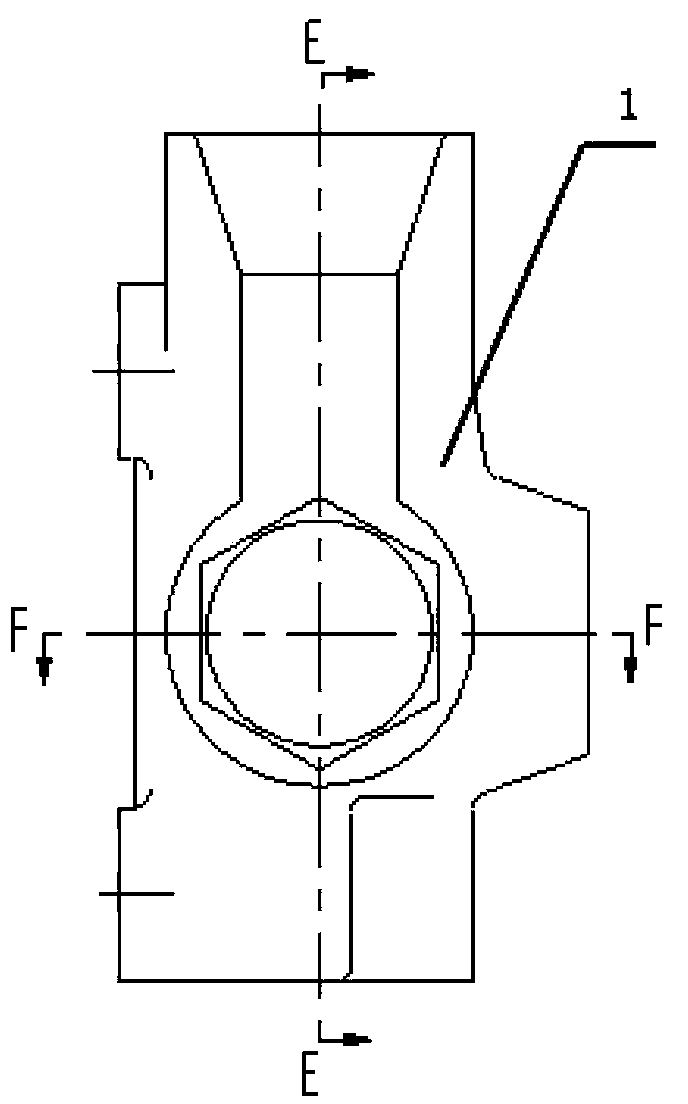
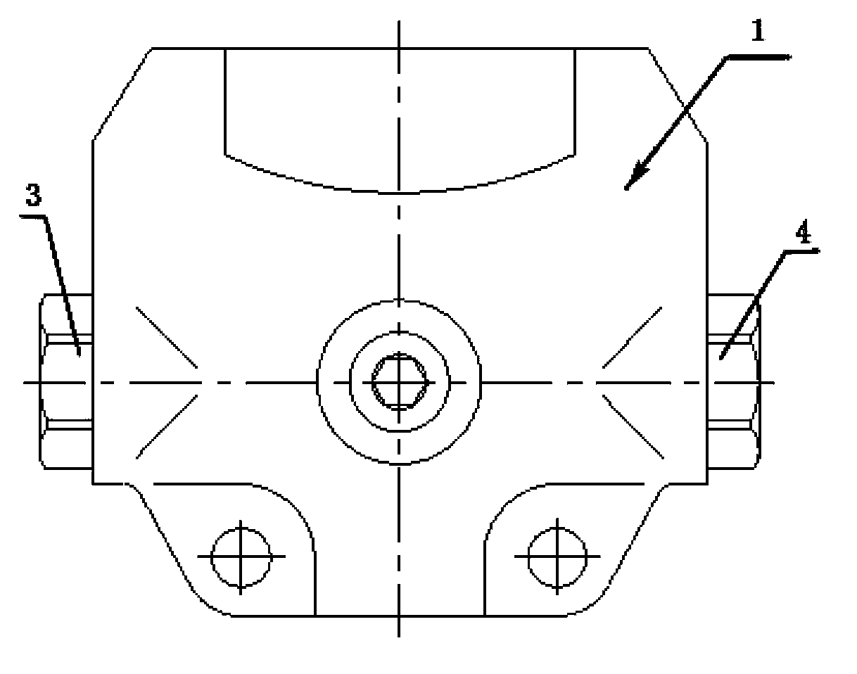
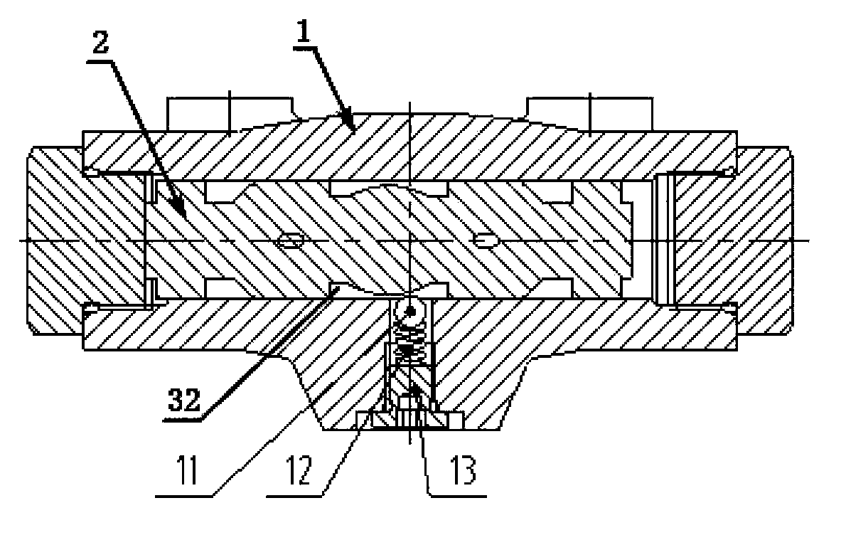
[0026] see Figure 1 to Figure 4 The differential pressure feedback diverter valve shown includes a valve body 1, a reversing valve core 2 matching with the valve body hole in the middle of the valve body 1, a first screw plug 3 matching with the left end of the valve body hole and The second screw plug 4 matched with the right end of the valve body hole, the right end of the first screw plug 3, the left end of the reversing valve core 2 and the inner wall of the left end of the valve body hole form the A cavity flow channel 29, and the second screw plug The left end of 4, the right end of the reversing valve core 2 and the inner wall of the right end of the valve body hole form a B chamber flow channel 30, and ring grooves are respectively arranged on the left and right parts of the reversing valve core 2, and the reversing valve core The middle part of th...


PUM


Abstract

The invention relates to a differential pressure feedback type flow divider valve. The differential pressure feedback type flow divider valve comprises a valve body, a reversing valve plug which is matched with a valve body hole formed in the middle of the valve body, a first screw plug which is matched with the left end of the valve body hole, and a second screw plug which is matched with the right end of the valve body hole, wherein a second flow channel which is slanted rightwards is formed in the left part of the middle of the reversing valve plug; a first flow channel is formed in the lower part of the valve body; one end of the first flow channel is communicated with a reversing cavity, and the other end of the first flow channel is communicated with an external hydraulic oil circuit; a first check valve is arranged on the left side of the upper part of the valve body; a second check valve is arranged on the right side of the upper part of the valve body; a damping hole is formed at the upper end of each of the first check valve and the second check valve; a positioning hole which is communicated with the valve body hole is also formed in the middle of the valve body; and a flow dividing positioning mechanism which is matched with a concave part on each of two sides of the reversing cavity is arranged in the positioning hole. The differential pressure feedback type flow divider valve is simple in structure and high in integration level.

Description

technical field [0001] The invention relates to components of a hydraulic control device, in particular to a differential pressure feedback diverter valve. Background technique [0002] The existing agricultural machines generally use the following two methods to control the circulation of the oil circuit: [0003] (1) The hydraulically controlled manual double reversing valve is used to realize the conversion and control of the movement direction of the actuator. When installing this kind of control device, in order to relieve the tension of the operator during operation, the operating mechanism will be installed according to the operating habits of different operators. Therefore, the actuator will also change its position with the adjustment of the operating mechanism, resulting in The installation is inconvenient, and this control device has low operating efficiency and high energy consumption, which can no longer meet the design requirements of modern agricultural mach...

Claims


Application Information

Patent Timeline
Patent Type & Authority Patents(China)
IPC IPC(8): F15B13/02
Inventor 陈启松徐光德
Owner 泸州众大科技液压件有限公司
Why Eureka
Try Eureka