Full-automatic water-steam separating energy-saving drain valve

A water vapor separation and steam trap technology, applied in steam traps, mechanical equipment, etc., can solve the problems of thermal efficiency reduction, equipment thermal energy loss, equipment thermal efficiency reduction, etc., to prevent stagnation and steam discharge, automatically adjust the discharge speed, reduce The effect of heat loss

Inactive Publication Date: 2013-01-30
廖海康
View PDF8 Cites 0 Cited by
  • Summary
  • Abstract
  • Description
  • Claims
  • Application Information

AI Technical Summary

Problems solved by technology

[0002] The interior of the existing steam trap is designed to seal the outlet tightly to achieve the effect of draining water but not steam. In fact, this is wrong. If the air pressure on the equipment is proportional to the air pressure of the steam trap, the condensed water will slowly flow in the equipment. Outflow causes the heat energy of the equipment to be absorbed by the condensate to reduce the heat energy of the equipment. If steam or non-condensable gas such as air enters the trap before the condensate is discharged, causing the trap outlet to close and preventing the normal discharge of condensate, causing stagnation. The thermal efficiency of the equipment is greatly reduced
The improved steam trap is to add an exhaust device to discharge the steam to drain the water. Although the addition of the exhaust device makes the trap work normally, the exhaust steam will cause waste of steam and not save energy.
[0003] The amount of condensed water is different when the equipment is just started and after a period of operation, and the fluctuation of the load of the equipment will also affect the amount of condensed water. The biggest problem in the design of the trap is to set the opening of the valve. The existing trap is for a The fixed opening cannot be increased with the increase of condensed water. When there is a lot of condensed water, it cannot be discharged in time. The accumulated condensed water will cause the heat loss of the equipment and reduce the thermal efficiency; if the condensed water is small, steam will leak and cause steam waste of

Method used


Image

  • Full-automatic water-steam separating energy-saving drain valve
  • Full-automatic water-steam separating energy-saving drain valve
  • Full-automatic water-steam separating energy-saving drain valve

Examples


Embodiment Construction

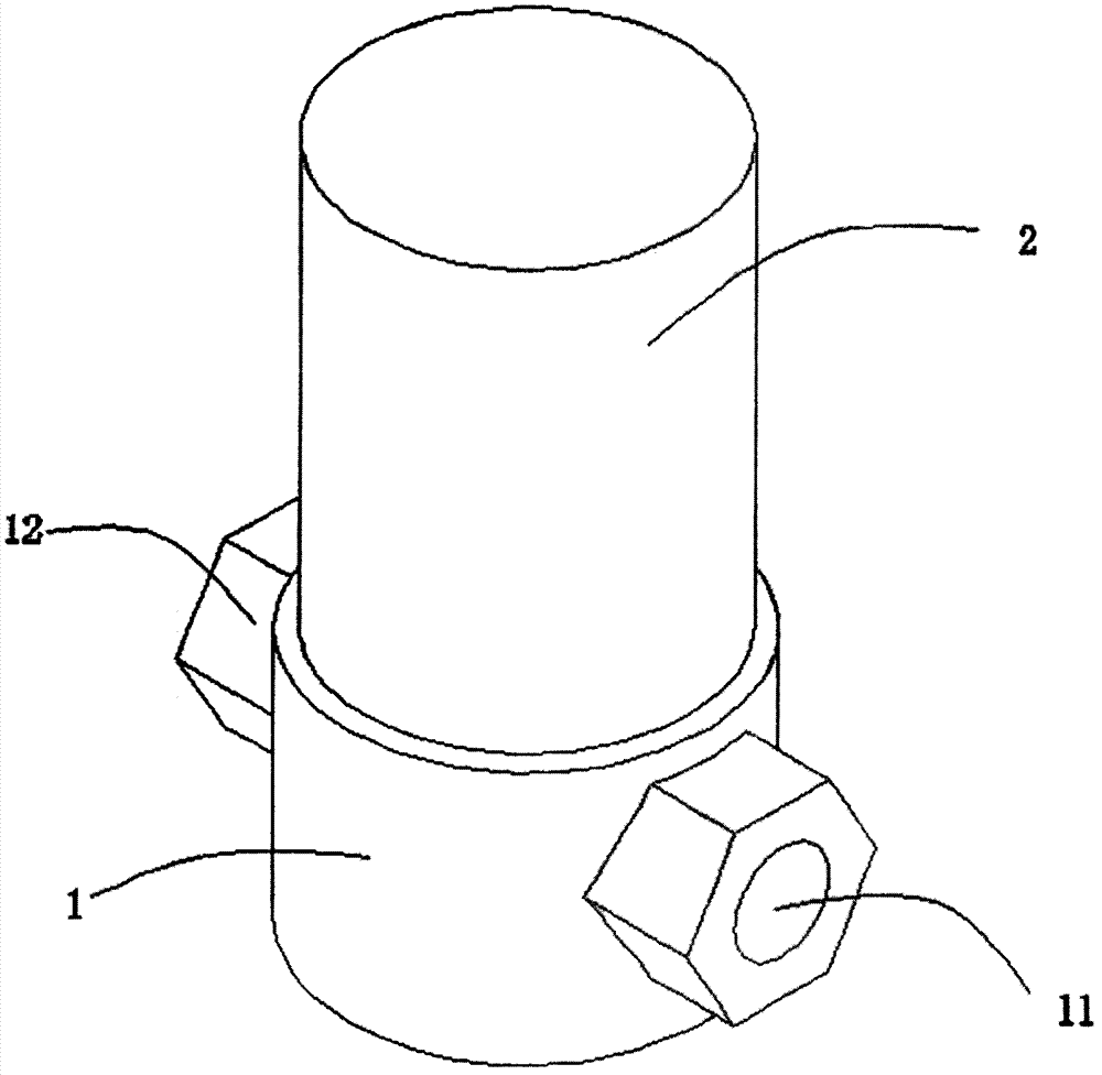
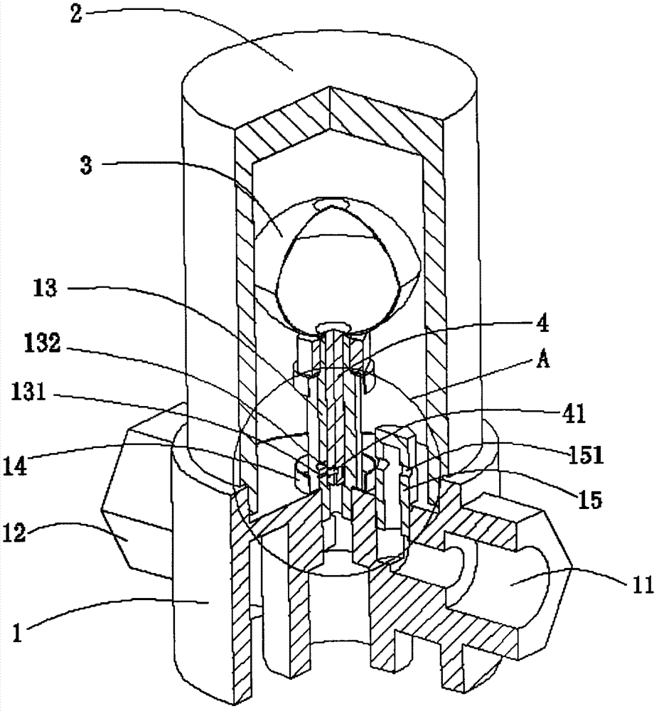
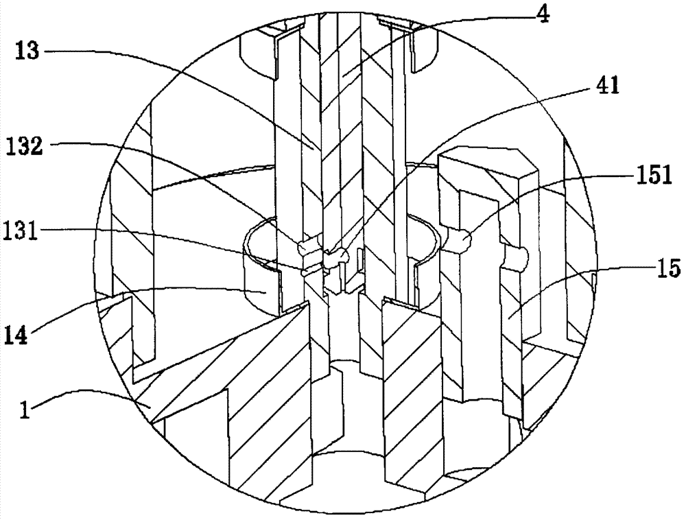
[0021] Such as Figure 1 to Figure 5 Shown: a fully automatic water vapor separation energy-saving steam trap of the present invention, comprising a valve body 1, a valve cover 2 and a valve ball 3, the valve body 1 is provided with an inlet 11 and an outlet 12, and the valve body 1 is provided with a discharge Valve seat 13, the discharge valve seat 13 is provided with a first discharge hole 131 and a second discharge hole 132, the discharge valve seat 13 is provided with a valve core 4, the valve ball 3 is fixed on the upper end of the valve core 4, and the valve core 4 can be moved by the valve ball 3 Driven to move up and down in the discharge valve seat 13 ; the valve core 4 is provided with a drainage channel 41 that can be aligned with the first discharge hole 131 or the second discharge hole 132 .

[0022] The first discharge hole 131 and the second discharge hole 132 are located on the side wall of the discharge valve seat 13; the diameter of the first discharge hole ...


PUM


Abstract

The invention relates to a full-automatic water-steam separating energy-saving drain valve which comprises a valve body, a valve bonnet and a valve ball. An inlet and an outlet are arranged on the valve body, the valve body and the valve bonnet form a cavity capable of accommodating condensate, a drain valve seat is arranged on the valve body and is provided with a first drain hole and a second drain hole, a valve spool capable of being driven by the valve ball and ascending and descending vertically in the drain valve seat is arranged in the drain valve seat, and a drainage channel capable of being aligned with the first drain hole or the second drain hole is arranged on the valve spool. Compared with the prior art, the full-automatic water-steam separating energy-saving drain valve has the advantages that the first drain hole and the second drain hole are arranged on the drain valve seat, the valve spool capable of being driven by the valve ball and ascending and descending vertically in the drain valve seat is arranged in the drain valve seat, the drain channel aligned with the first drain hole is arranged on the valve spool, condensate can be drained via the first drain hole of the drain valve seat when the quantity of the condensate is low, and when the quantity of the condensate is high, the valve ball can ascend to drive the valve spool to ascend, and the first drain hole and the second drain hole drain the condensate simultaneously, accordingly, the condensate drainage speed can be automatically adjusted, the condensate can be drained continuously, condensate stagnation and steam discharge are effectively prevented, heat loss of equipment is reduced, the heat efficiency is improved, and energy is saved.

Description

technical field [0001] The invention relates to a drain valve, in particular to a fully automatic water vapor separation energy-saving drain valve. Background technique [0002] The interior of the existing steam trap is designed to seal the outlet tightly to achieve the effect of draining water but not steam. In fact, this is wrong. If the air pressure on the equipment is proportional to the air pressure of the steam trap, the condensed water will slowly flow in the equipment. Outflow causes the heat energy of the equipment to be absorbed by the condensate to reduce the heat energy of the equipment. If steam or non-condensable gas such as air enters the trap before the condensate is discharged, causing the trap outlet to close and preventing the normal discharge of condensate, causing stagnation. The thermal efficiency of the equipment is greatly reduced. The improved steam trap is to add an exhaust device to discharge the steam to drain the water. Although the addition of...

Claims


Application Information

Patent Timeline
Patent Type & Authority Applications(China)
IPC IPC(8): F16T1/20
Inventor 廖海康
Owner 廖海康
Why Eureka
Try Eureka