Drying device

A drying device and drying cylinder technology, applied in drying, drying machine, drying solid materials and other directions, can solve problems such as unfavorable processing, rust, time-consuming, etc., and achieve the effect of convenient operation

Inactive Publication Date: 2013-01-30
ZHONGSHAN OMS AUTOMATION EQUIP
View PDF5 Cites 4 Cited by
  • Summary
  • Abstract
  • Description
  • Claims
  • Application Information

AI Technical Summary

Problems solved by technology

The cleaned U-shaped tube still contains a lot of water. If the U-shaped tube is left to dry freely in the air, it will not only take time but also rust, which is not conducive to subsequent processing

Method used


Image

  • Drying device
  • Drying device
  • Drying device

Examples


Embodiment

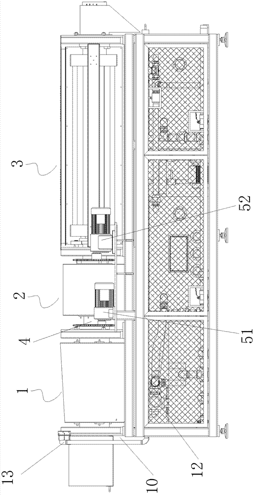
[0023] Embodiment: A cleaning machine includes a frame 10 and a cleaning device 1, a liquid removal device 2, and a drying device 3 which are sequentially installed on the frame 10.

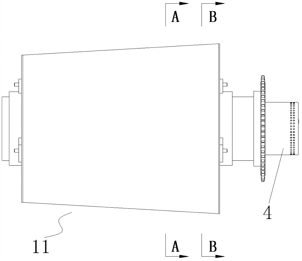
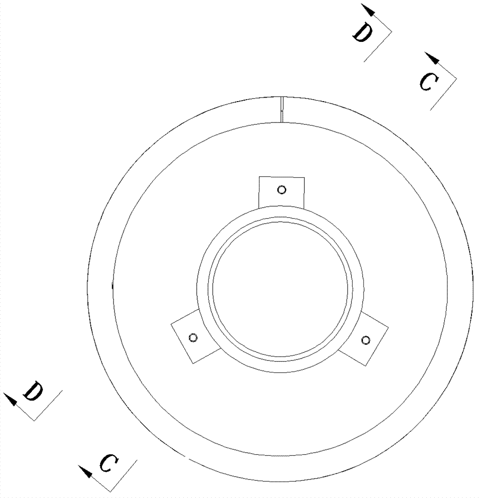
[0024] The cleaning device 1 includes a cleaning cylinder 11, which includes a cleaning cylinder 11-1 in the shape of a cone that can rotate around a horizontal axis, and a left end plate and a right end plate installed at both ends of the cleaning cylinder 11-1. The body 11-1 is evenly distributed with screen holes (not shown in the figure). The center of the left end plate on the smaller diameter side of the cleaning cylinder 11-1 is provided with a cleaning feed inlet 11-2, and the center of the right end plate is provided with a cleaning Outlet 11-3. A water tank 12 is installed under the cleaning cylinder 11, and a water spray pipe 13 extends from the cleaning feed inlet 11-2 and is suspended in the inner cavity of the cleaning cylinder 11-1. The cleaning machine is equipped with two water spra...


PUM


Abstract

The invention relates to a drying device, in particular to a drying device for drying a U-shaped tube. The drying device comprises a material conveying device and a heating device. The material conveying device comprises a drying cylinder which can rotate around a horizontal axis and a spiral flange plate which is mounted in the drying cylinder and is used for material guiding, and the heating device is mounted outside the drying cylinder. The drying device has the advantages that water on the U-shaped tube can be dried automatically, and the drying device is convenient to operate, safe and reliable.

Description

(1) Technical field [0001] The invention relates to a drying device, in particular to a drying device for drying a U-shaped tube. (2) Background technology [0002] The production of heat exchangers requires a large number of U-shaped tubes, and the U-shaped tubes generate a lot of burrs and oil stains during the production process, which need to be cleaned. The method currently used is mainly manual operation. After spraying a large amount of cleaning fluid on the U-shaped tube, it is cleaned with clean water. The cleaned U-shaped tube still contains a lot of moisture. If the U-shaped tube is left in the air to dry freely, it will not only take time but also rust, which is not conducive to subsequent processing. (3) Summary of the invention [0003] In order to solve the above problems, the present invention provides a drying device, which can automatically dry the moisture on the U-shaped tube, and is convenient, safe and reliable to operate. [0004] To this end, the present in...

Claims


Application Information

Patent Timeline
Patent Type & Authority Applications(China)
IPC IPC(8): F26B17/30F26B3/30
Inventor 龙晓斌焦大勇
Owner ZHONGSHAN OMS AUTOMATION EQUIP
Why Eureka
Try Eureka