Self-locking telescopic clothes hanger with pure mechanical structure

A purely mechanical and garment support technology, applied in the field of self-locking and retractable garment supports, can solve the problems of time-consuming and inconvenient drying and picking of clothes with small necklines, and achieve the effects of improving efficiency, hanging and drying reliably, and quickly removing clothes

Inactive Publication Date: 2020-05-19
HARBIN INST OF TECH
View PDF4 Cites 0 Cited by
  • Summary
  • Abstract
  • Description
  • Claims
  • Application Information

AI Technical Summary

Problems solved by technology

[0003] In order to solve the problem that clothes hangers in the prior art are inconvenient to dry and remove clothes with small necklines, resulting in a time-consuming drying process, the present invention further provides a self-locking stretchable clothes hanger with a purely mechanical structure ;

Method used


Image

  • Self-locking telescopic clothes hanger with pure mechanical structure
  • Self-locking telescopic clothes hanger with pure mechanical structure
  • Self-locking telescopic clothes hanger with pure mechanical structure

Examples


specific Embodiment approach 1

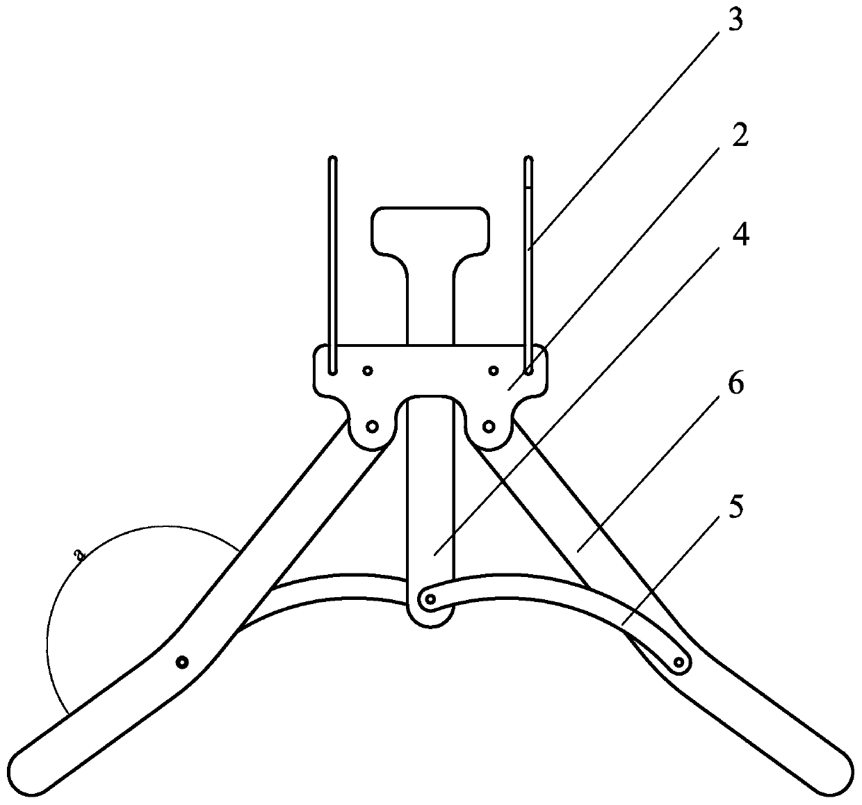
[0026] Specific implementation mode one: refer to figure 1 and Figure 4 Describe this embodiment, this embodiment provides a purely mechanical structure self-locking telescopic clothing support, the clothing support includes a suspension mechanism, a support mechanism and an adjustment mechanism, the support mechanism is arranged below the suspension mechanism, and supports The mechanism is hinged with the suspension mechanism, the adjustment mechanism is inserted on the suspension mechanism, and the adjustment mechanism is slidingly connected with the suspension mechanism, and the adjustment mechanism is hinged with the support mechanism.

specific Embodiment approach 2

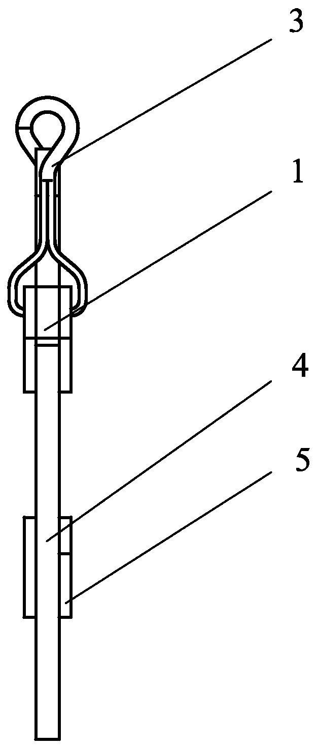
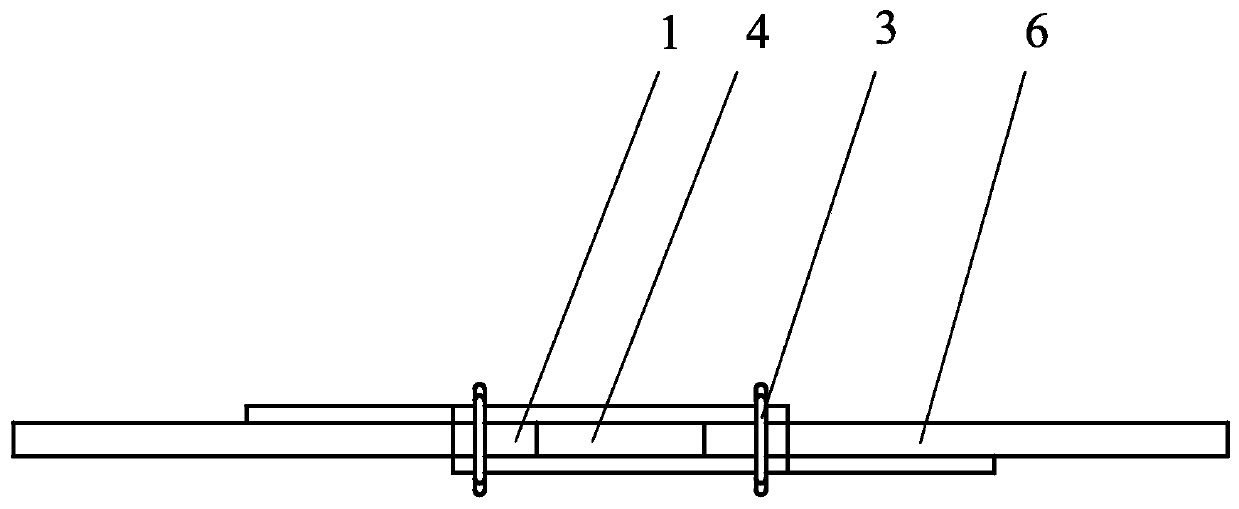
[0027] Specific implementation mode two: refer to figure 1 and figure 2 Describe this embodiment, this embodiment is to further limit the suspension mechanism described in the first specific embodiment, in this embodiment, the suspension mechanism includes a spacer 1, two splints 2 and two clothes hooks 3, the Two splints 2 are relatively arranged on both sides of the cushion block 1, and each splint 2 is fixedly connected with the cushion block 1, and the two clothes hooks 3 are respectively arranged at both ends of the cushion block 1, and each clothes hook 3 is connected with the cushion block 1. The pads 1 are connected, and the middle part of the upper surface of the pad 1 is processed with a through hole. Other compositions and connection methods are the same as those in Embodiment 1.

specific Embodiment approach 3

[0028] Specific implementation mode three: refer to figure 1 and Figure 4 Describe this embodiment. This embodiment is to further limit the splint 2 described in the second specific embodiment. In this embodiment, the lower part of each splint 2 is provided with two connecting ears, one splint 2 and two connecting ears All in one setting. Other compositions and connection methods are the same as those in the second embodiment.

[0029] In this embodiment, the connection ear is provided for better hinged connection with the support rod 6, so as to prevent the support rod 6 from being directly connected with the cushion block 1, which will affect the action stroke during work.


PUM


Abstract

The invention, whichbelongs to the field of self-locking hanger manufacturing, discloses a self-locking telescopic clothes hanger with a pure mechanical structure, thereby solving a problem that a clothes hanger in the prior art is inconvenient to air and pick up clothes with small collars and thus more time is consumed in the airing process. The clothes hanger comprises a hanging mechanism, a supporting mechanism and an adjusting mechanism; the supporting mechanism is arranged below the hanging mechanism, the supporting mechanism is hinged to the hanging mechanism, the adjusting mechanism isinserted into the hanging mechanism, the adjusting mechanism is in sliding connection with the hanging mechanism, and the adjusting mechanism is hinged to the supporting mechanism. The clothes hangeris mainly applied to airing and displaying of clothes with small collars.

Description

technical field [0001] The invention belongs to the field of self-locking clothes hanger manufacturing, in particular to a self-locking telescopic clothes hanger with a purely mechanical structure. Background technique [0002] Home drying or batch laundry drying in factories, being able to efficiently and conveniently dry and collect clothes is a current hot spot, and saving people’s time is an increasingly important demand. Batch production is not convenient for drying and picking clothes, especially clothes with small necklines, which makes drying inconvenient and takes a long time in the drying process. At the same time, it causes uneven space when drying clothes, which affects the final drying effect , so developing a purely mechanical self-locking telescopic clothing support is very much in line with actual needs. Contents of the invention [0003] In order to solve the problem that clothes hangers in the prior art are inconvenient to dry and remove clothes with sma...

Claims


Application Information

Patent Timeline
IPC IPC(8): A47G25/44A47G25/32
CPCA47G25/325A47G25/441
Inventor 陈超赵扬于良刘子毅任思齐王滨生
Owner HARBIN INST OF TECH
Why Eureka
Try Eureka