Device for separating melting impurities during pig iron separation and reduction

A technology of melting and pig iron, which is applied in the direction of mechanical cleaning, manufacturing tools, metal processing equipment, etc., can solve the problems of low work efficiency and poor filtering effect of molten iron, so as to improve work efficiency, facilitate work, and have good filtering effect Effect

Active Publication Date: 2021-03-12
江苏长实基业电气科技有限公司
View PDF13 Cites 0 Cited by
  • Summary
  • Abstract
  • Description
  • Claims
  • Application Information

AI Technical Summary

Problems solved by technology

[0004] In order to overcome the disadvantages of poor filtering effect and low working efficiency of the existing technology on molten iron, the technical problem to be solved is: to provide a device for separating molten impurities during the separation and reduction of pig iron with good impurity removal effect and high working efficiency

Method used


Image

  • Device for separating melting impurities during pig iron separation and reduction
  • Device for separating melting impurities during pig iron separation and reduction
  • Device for separating melting impurities during pig iron separation and reduction

Examples


Embodiment 1

[0078] A device for separating molten impurities when reducing pig iron, such as figure 1 As shown, it includes a base plate 1, a servo motor 2, a filter mechanism 3 and a knocking mechanism 4. The servo motor 2 is provided on the front right of the top of the base plate 1, and a filter is provided between the left side of the top of the base plate 1 and the output shaft of the servo motor 2. Mechanism 3, a percussion mechanism 4 is provided between the top right side of the bottom plate 1 and the filter mechanism 3.

[0079] When people need to filter molten iron, first start the servo motor 2, the output shaft of the servo motor 2 drives the filter mechanism 3 to rotate, when a certain part of the filter mechanism 3 rotates to a certain position, pour the molten iron into a certain part of the filter mechanism 3 Among the components, the filter mechanism 3 filters the molten iron, and then collects the filtered molten iron. When a certain part of the filter mechanism 3 rotat...

Embodiment 2

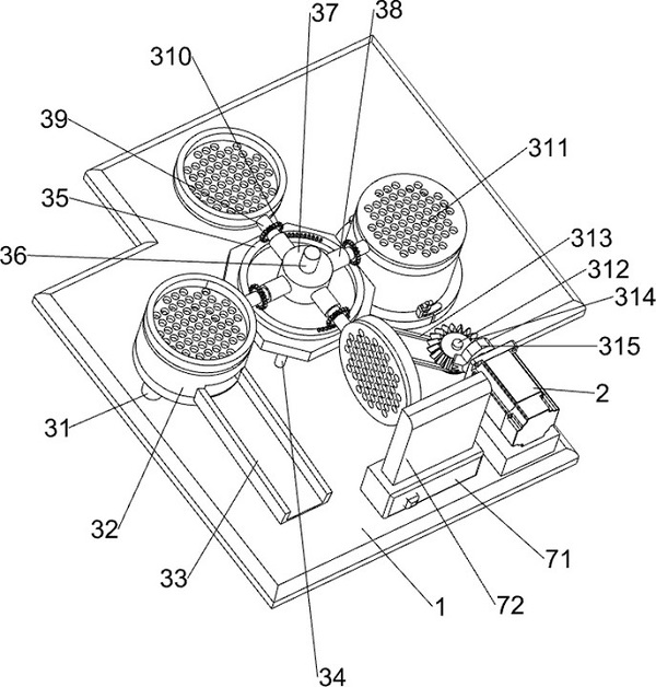
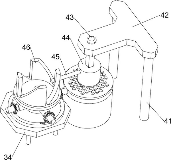
[0081] On the basis of Example 1, such as figure 2 , image 3 with Figure 4 As shown, the filter mechanism 3 includes a first support column 31, a first blanking basket 32, a channel 33, a support plate 34, a ring rack 35, a first rotating shaft 36, a first connecting block 37, and a first connecting rod 38 , the second connecting rod 39, the first gear 310, the filter plate 311, the second rotating shaft 312, the pulley group 313, the bevel gear 314 and the missing gear 315, the rear part of the top left side of the bottom plate 1 is symmetrically provided with the first support column 31 , a first blanking basket 32 ​​is arranged between the tops of the first supporting columns 31, a channel 33 is provided at the left front part of the top of the bottom plate 1, the upper rear side of the channel 33 is connected with the lower front side of the first blanking basket 32, and the top of the bottom plate 1 The left side is provided with support plate 34, and support plate 3...

Embodiment 3

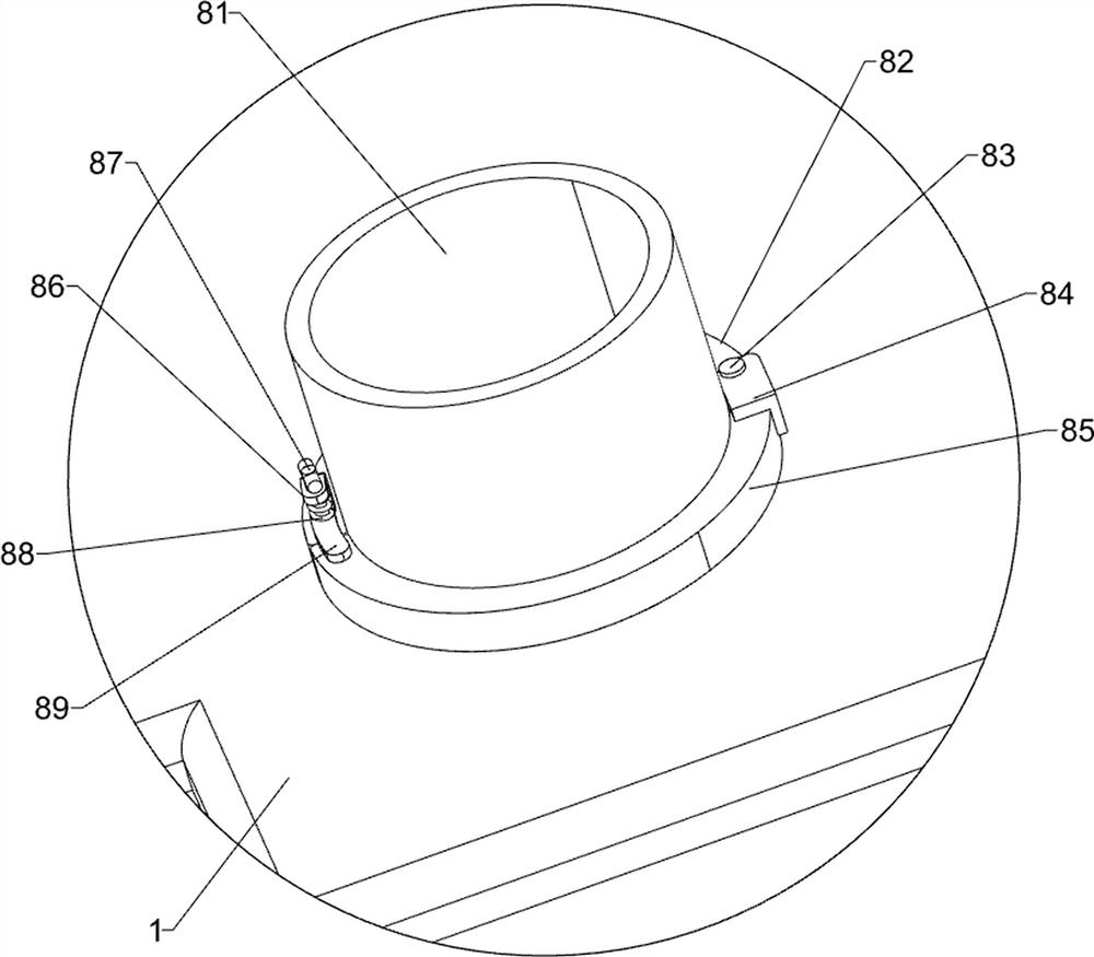
[0088] On the basis of Example 2, such as figure 2 , Figure 5 with Image 6 As shown, a cooling mechanism 6 is also included, and the cooling mechanism 6 includes a fourth support column 61, a water receiving bucket 62, a water tank 63, a fixed block 64, a pipe 65, a water pump 66, a water pipe 67 and a spray nozzle 68, and the rear side of the top of the bottom plate 1 The front and rear sides of the left part are provided with two fourth support columns 61, a water bucket 62 is arranged between the tops of the fourth support columns 61, a water tank 63 is arranged on the right side of the top rear side of the bottom plate 1, and a water tank 63 is arranged on the rear side of the bottom plate 1 top. The right part is left and right symmetrically provided with fixed block 64, and bottom plate 1 top rear right part is provided with water pump 66, and the left and right sides of water pump 66 are all provided with pipe 65, and pipe 65 all passes through the fixed block 64 of...


PUM


Abstract

The invention relates to a device for separating melting impurities, in particular to a device for separating melting impurities during pig iron separation and reduction. The invention provides the device for separating melting impurities during pig iron separation and reduction, which is good in impurity removal effect and is high in work efficiency. The device for separating melting impurities during pig iron separation and reduction comprises a bottom plate and a servo motor as well as a filter mechanism and a knocking mechanism, wherein the servo motor is arranged at one side of the top ofthe bottom plate; the filter mechanism is arranged between one side of the top of the bottom plate and the output shaft of the servo motor; and the knocking mechanism is arranged between one side ofthe top of the bottom plate and the filter mechanism. An indirect discharge mechanism, the knocking mechanism and the filter mechanism are matched, so that intermittent discharge and filter operationof molten iron can be automatically accomplished, work efficiency of people is improved, amount of molten iron filtered every time is less, and filter effect on molten iron is good; and a cooling mechanism can automatically cool the filtered impurities, so that a knocking block conveniently knocks off the impurities adhered onto a filter plate.

Description

technical field [0001] The invention relates to a device for separating molten impurities, in particular to a device for separating molten impurities when reducing pig iron. Background technique [0002] Generally speaking, molten iron for casting will contain some impurities. According to the current technology, people will use slag remover to remove impurities from molten iron, but because the slag remover can only remove impurities floating to the surface of molten iron, There will still be impurities in the molten iron after the deslagging agent. [0003] In foundry production, filters or filter screens are generally used to filter impurities in molten iron. When there is a lot of slag in molten iron, the filter seat is easily blocked, reducing the flow of molten iron, thus causing the casting to be scrapped. At this time, the molten iron needs to be filtered again, which will waste a lot of time for people, thereby affecting people's work efficiency. Therefore, no matt...

Claims


Application Information

Patent Timeline
IPC IPC(8): B22D43/00
CPCB22D43/004
Inventor 孔燕芳
Owner 江苏长实基业电气科技有限公司
Why Eureka
Try Eureka