Rock drilling rig, method and speed controller for a transfer drive of a rock drilling rig

A technology for rock drilling rigs and driving equipment, which is applied to road vehicle drive control systems, drilling equipment and methods, motor vehicles, etc., can solve the problems of reducing the transfer driving speed, reducing the performance of rock drilling rigs, etc., so as to improve operability and safety. safety, avoid the effect of super-safety standard design

Inactive Publication Date: 2016-01-20
SANDVIK MINING & CONSTR OY
View PDF5 Cites 0 Cited by
  • Summary
  • Abstract
  • Description
  • Claims
  • Application Information

AI Technical Summary

Problems solved by technology

Due to power limitations, the speed of the transfer drive has to be reduced, which reduces the performance of the rock drilling rig

Method used


Image

  • Rock drilling rig, method and speed controller for a transfer drive of a rock drilling rig
  • Rock drilling rig, method and speed controller for a transfer drive of a rock drilling rig
  • Rock drilling rig, method and speed controller for a transfer drive of a rock drilling rig

Examples


Embodiment Construction

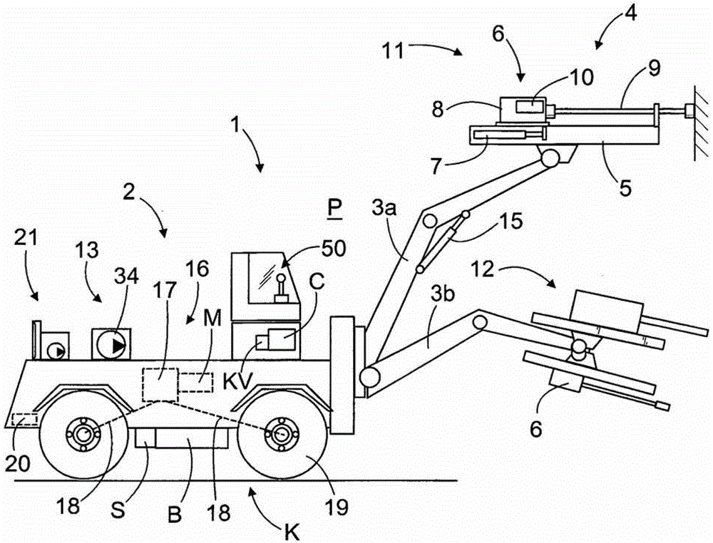
[0035] figure 1A possible rock drilling rig 1 is shown comprising a movable carrier 2 in which one or more booms 3a, 3b equipped with a rock drilling unit 4 are arranged. The drilling unit 4 may comprise a feed beam 5 , to which a rock drilling machine 6 is arranged movable on the feed beam 5 by means of a feed device 7 . The rock drilling machine 6 may comprise percussion means 8 for generating impact pulses on the tool 9 and rotation means 10 for rotating the tool 9 . Furthermore, the rock drilling machine 6 may comprise flushing means. The boom 3a shown in the figure and the drilling unit 4 arranged thereto are intended for drilling a borehole in a drilling face 11 of a tunnel or a corresponding drilling site. Alternatively, the boom and the drilling unit thereon can be designed for drilling fan-shaped boreholes in the roof and walls of the rock cavern. Furthermore, the rock drilling machine 1 comprises a boom 3 b provided with a bolt connection 12 , the boom 3 b also co...


PUM


Abstract

The invention relates to a rock drilling rig, a method for a transfer drive of the rock drilling rig and a speed controller. The rock drilling rig (1) comprises a drive without an internal combustion engine (16) comprising a plurality of electrical components (K) for implementing a transfer drive. The control unit (C) of the rock drilling rig comprises a load monitor (KV) which monitors the load of the components during the transfer drive. Load monitoring allows intentional overloading of the electric drive system for a defined period of time in advance. The user interface of the control unit comprises a speed controller (50), the control element (51) of the speed controller (50) has: a first control range (53), in which operation takes place within the rated load range; and a second control range(54), where the operation occurs within the overload range.

Description

technical field [0001] The invention relates to a rock drilling rig comprising a boom provided with a rock drilling machine so that drilling can thus be performed at a selected drilling site. The rock drilling rig also includes a drive without an internal combustion engine by which the rock drilling rig can be transferred between drilling sites. A drive arrangement for a rock drilling rig comprises at least one electric motor and an electric drive system, and also comprises a control unit comprising means for controlling the load of the electric drive system. In addition, the control unit includes a user interface with a speed controller. [0002] Furthermore, the invention relates to a method and a speed controller for a transfer drive of a rock drilling rig. [0003] The field of the invention is described in more detail in the preambles of the independent claims of this patent application. Background technique [0004] Rock drilling rigs are used in mines to drill bore...

Claims


Application Information

Patent Timeline
Patent Type & Authority Patents(China)
IPC IPC(8): B60L15/20B60W30/18B60W50/08B60W50/14
CPCB60Y2200/41B60Y2200/91B60Y2300/67E21B7/025B60L2200/40B60L2240/36B60L2260/16Y02P90/60Y10T74/20396B60W30/18B60W50/08B60L15/20Y02T10/72B60W50/14
Inventor 亚尔诺·库伊蒂宁尤卡·奥萨拉
Owner SANDVIK MINING & CONSTR OY
Why Eureka
Try Eureka