Shrink tunnel

A technology of shrinking channel and shrinking medium, which is applied in the direction of wrapping paper shrinking, wrapping, wrapping paper, etc., and can solve problems such as defective packaging, uneven drainage area of ​​hot air 40, etc.

Active Publication Date: 2013-02-06
KRONES AG
View PDF9 Cites 4 Cited by
  • Summary
  • Abstract
  • Description
  • Claims
  • Application Information

AI Technical Summary

Problems solved by technology

Here, there is the risk that, for example, stacked foils pointing upwards could be pressed down by a downwardly directed air flow

Method used


Image

  • Shrink tunnel
  • Shrink tunnel
  • Shrink tunnel

Examples


Embodiment Construction

[0041] The same reference numerals are used for identical or functionally identical elements of the invention. Furthermore, for reasons of clarity, only the reference signs required for the description of the respective figure are shown in the individual figures. The embodiments shown are merely examples of how the device according to the invention and the method according to the invention are designed and are not intended to represent a closed limitation.

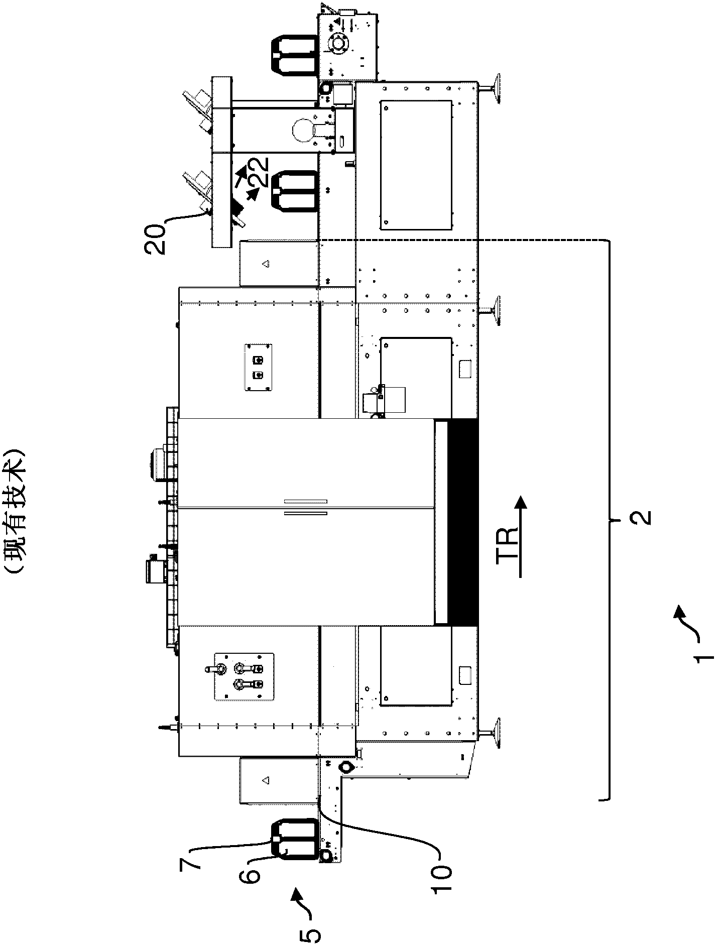
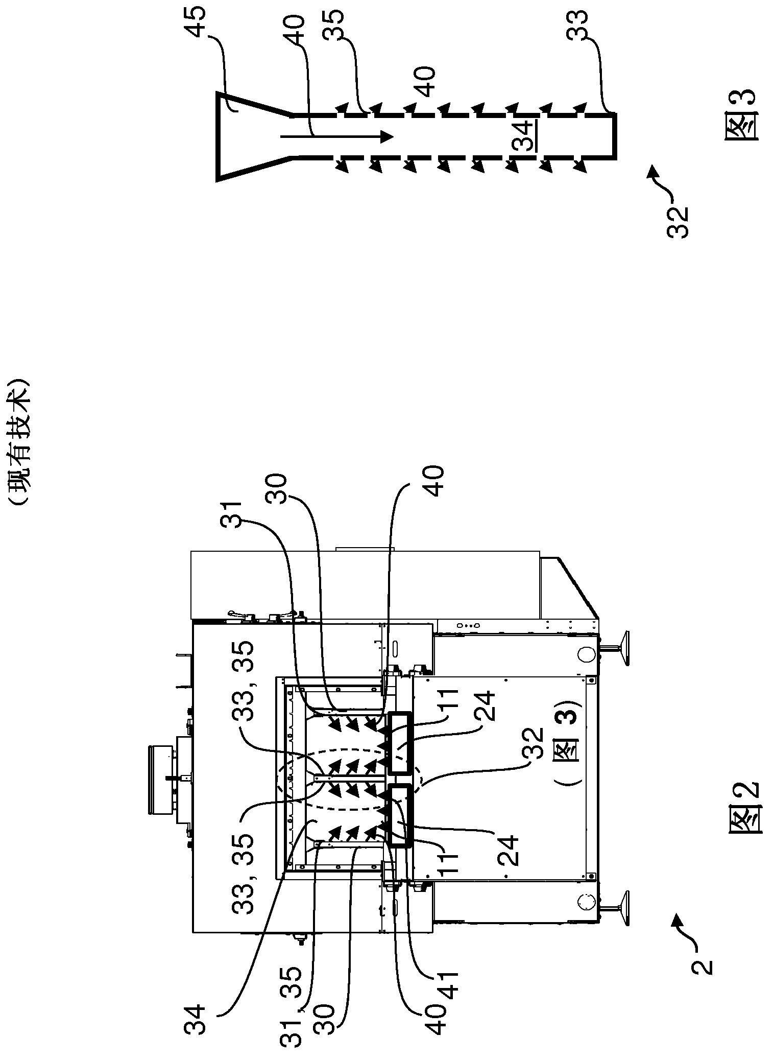
[0042] Figures 1 to 3 It has been introduced in the prior art.

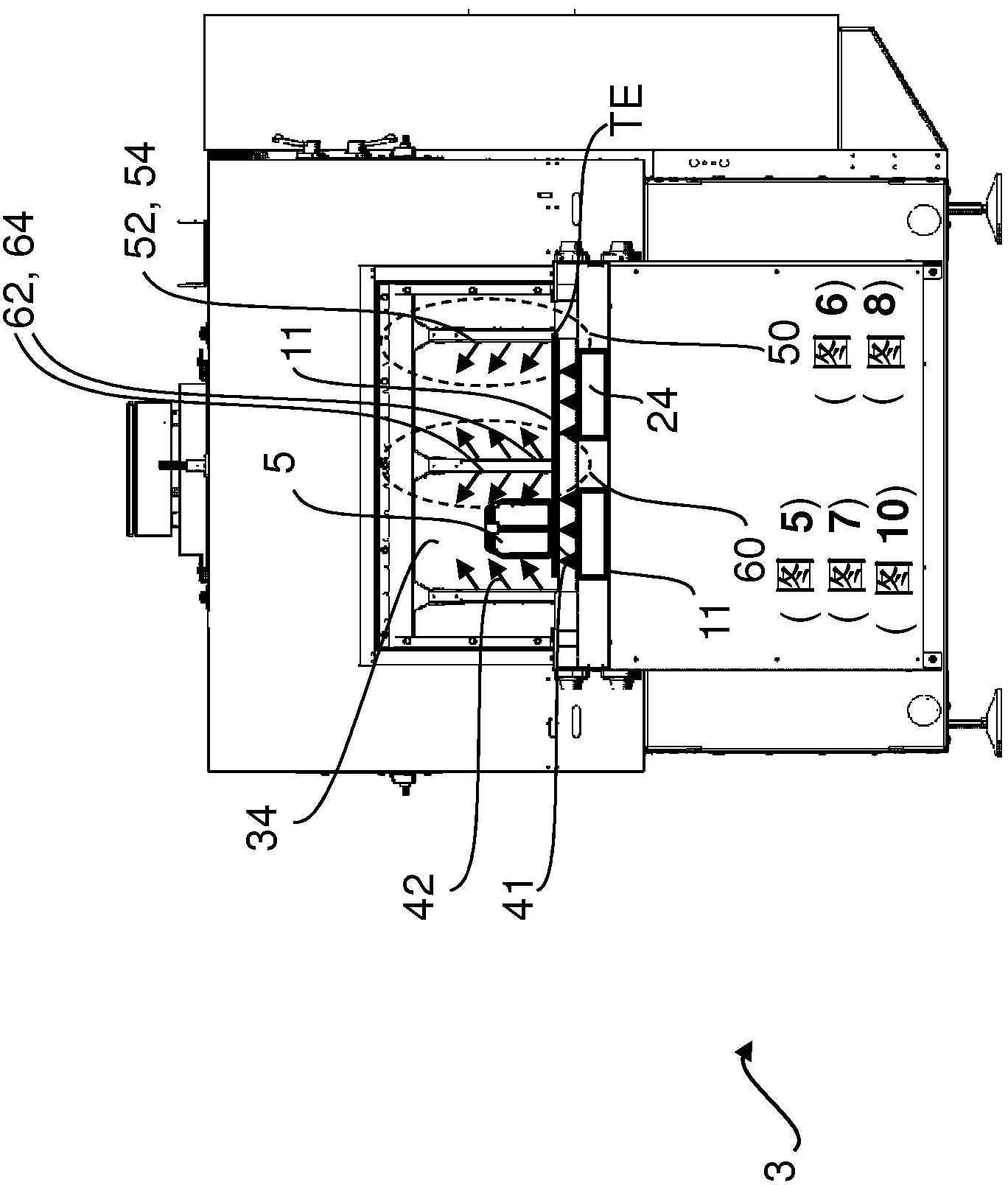
[0043] Figure 4 A sectional view of the constriction channel 3 with an inner cylinder wall 60 modified according to the invention and an outer cylinder wall 50 modified according to the invention is shown. The shrink tunnel 3 comprises two conveying tracks 11 for the bundles 5 of articles. A hot air generator 24 is arranged below the transport plane TE. Hot air 41 is used as a shrinking medium and is directed upwards through the conveying plane towards...


PUM


Abstract

The present invention relates to a shrink tunnel for enabling a packaging material wrapping article aggregation to shrink, and a method for enabling a packing material wrapping goods aggregation to shrink. The shrink channel comprises: at least one conveyor belt used for articles wrapped in the packaging material; and at least two shaft walls arranged on both sides with respect to the conveyor belt, shrink medium is guided to the shrink film of the wrapped articles through these shaft walls. The shrink medium is generated by means of a fan (for example, by means of a hot-air blower), and is introduced into the shaft walls from above. The shrink medium is introduced into the shrink tunnel, through nozzle openings arranged in the side surface of the shaft walls perpendicular to the conveyor belt. According to the present invention, the shaft walls include at least one deflecting device used for the shrink medium. Flow directions of the shrink medium are reversed by the deflecting device. The shrink tunnel of the present invention has a favorable flow direction, in order to circumvent the disadvantages of known arrangement schemes.

Description

technical field [0001] The invention relates to a shrink tunnel for shrinking a packaging material surrounding a collection of objects, wherein the shrink tunnel comprises at least one conveying plane and at least two cylinder walls, wherein the conveying plane has a function for wrapping with packaging material The conveying section of the article, and the article wrapped in packaging material can be loaded with shrinking medium through the wall of the cylinder. Furthermore, the invention relates to a method for shrinking a packaging material surrounding a collection of objects, wherein a shrinking medium is introduced from the cylinder wall into the shrinking channel. Background technique [0002] Methods and devices are known from the prior art for packaging objects (packages) which use shrink films as wrappings for objects. Shrink films of this type are generally wound as film cutouts around the assembly of goods by means of a packaging system. This so-called collectio...

Claims


Application Information

Patent Timeline
IPC IPC(8): B65B53/06
CPCB65B53/063
Inventor 克里斯蒂安·纳普拉夫尼克
Owner KRONES AG
Why Eureka
Try Eureka