Oil separator
An oil separator and oil return pipe technology, applied in refrigeration components, refrigerators, lighting and heating equipment, etc., can solve problems such as low separation efficiency and lack of filters, reduce volume, improve efficiency, and ensure reliable and stable operation. Effect
Active Publication Date: 2013-02-06
QINGDAO HISENSE HITACHI AIR CONDITIONING SYST
View PDF7 Cites 11 Cited by
- Summary
- Abstract
- Description
- Claims
- Application Information
AI Technical Summary
Problems solved by technology
However, the oil separator with this structure in the prior art has low separation efficiency due to the lack of components such as filter screens and partitions inside.
Method used
View moreImage
Smart ImageViewing Examples

Examples
Embodiment 1
Embodiment 2
Embodiment 3
Login to View More PUM
 Abstract
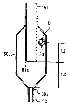
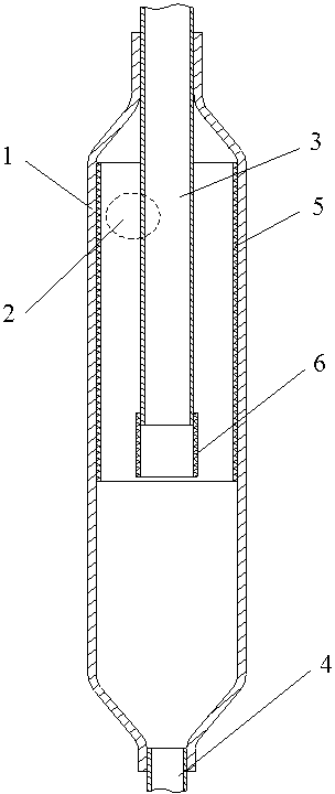
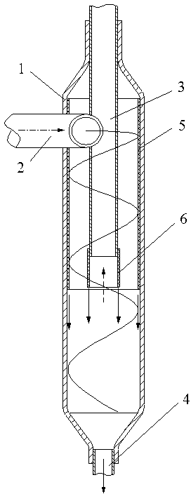
The invention discloses an oil separator, belonging to the separating device; the technical problem solved by the invention is to provide an oil separator, which has the characteristics of removing parts including a filter screen, a baffle plate and the like, reducing the inlet and outlet pressure loss, and fully reducing the volume. The technical scheme of the oil separator is that the oil separator comprises a cylinder body 1, as well as an intake tube 2, an exhaust tube 3 and an oil return tube 4 which are connected with the cylinder body 1; the cylinder body 1 comprises a straight tube part with a certain length and a tapered necking part reduced to both ends respectively; the exhaust tube 3 and the oil return tube 4 are respectively connected with an upper tapered necking port and a lower tapered necking port of the cylinder body 1; and the inner wall of the cylinder body is provided with a cylinder body liquid-collecting network 5. According to the oil separator, the inlet and outlet pressure loss of oil is reduced, and the volume of an oil-gas separator is reduced simultaneously, so that miniaturization design of an air conditioning system is facilitated, the oil amount of a heat exchanger is reduced, and the heat exchange effect is improved; the oil return of a compressor is timely and adequate, therefore, the reliable and stable operation of the compressor is ensured.
Description
technical field [0001] The invention relates to a separation device, in particular to an oil separator. Background technique [0002] The efficiency of the oil separator has always been a key factor affecting the overall performance of many equipment. The low efficiency of the oil separator will lead to too much oil entering the heat exchanger, forming an oil film inside the heat exchanger, increasing the heat transfer resistance, It will affect the heat exchange effect; it will also lead to too little oil returned to the compressor, increase the internal wear of the compressor, and affect the life and reliability of the compressor. Therefore, there is an urgent need to improve the efficiency of the oil separator. In addition, with the needs of life and production, many equipment tend to be more and more miniaturized, so it is required that various accessories including oil separators should also be miniaturized. However, there are many auxiliary parts such as filter scre...
Claims
Login to View More Application Information
Patent Timeline
 Patent Type & Authority Applications(China)
IPC IPC(8): F25B43/02
Inventor 辛电波张文强银松
Owner QINGDAO HISENSE HITACHI AIR CONDITIONING SYST
Features
- R&D
- Intellectual Property
- Life Sciences
- Materials
- Tech Scout
- Unparalleled Data Quality
- Higher Quality Content
- 60% Fewer Hallucinations
Learn More Browse by: Latest US Patents, China's latest patents, Technical Efficacy Thesaurus, Application Domain, Technology Topic, Popular Technical Reports.
© 2025 PatSnap. All rights reserved.Legal|Privacy policy|Modern Slavery Act Transparency Statement|Sitemap|About US| Contact US: help@patsnap.com