Method for electrically simulating mechanical inertia

A mechanical inertia, electrical simulation technology, applied in the direction of machine gear/transmission mechanism testing, etc., can solve the problems of difficult inertia adjustment, low degree of automation, simulation level difference, etc., to improve the accuracy of inertia simulation, improve the degree of automation, and simplify the mechanical structure. Effect

Inactive Publication Date: 2013-02-06
SOUTHEAST UNIV
View PDF6 Cites 17 Cited by
  • Summary
  • Abstract
  • Description
  • Claims
  • Application Information

AI Technical Summary

Problems solved by technology

The disadvantage of mechanical flywheel simulation inertia is that there are shortcomings such as simulation level difference and inertia adjustment difficulty, and the large-mass flywheel has high requirements for manufacturing processes such as machining accuracy and dynamic balance. In addition, the kinetic energy stored in the high-inertia flywheel rotating at high speed There is a certain danger to the equipment and test personnel. In order to simulate the inertia simulation requirements of different models, it is necessary to design the flywheel part into a flywheel set composed of multiple flywheels of different sizes according to the differential or proportional series, which increases the Complexity of the test bench and low degree of automation
Electric simulation is to use the torque or speed control characteristics of the loading motor in the test bench to simulate the energy storage characteristics of the mechanical flywheel by adjusting the system and the computer to control its mechanical energy and electric energy conversion characteristics, and act on the main shaft in the form of inertial torque, so that the test The dynamic characteristics of the bench are consistent with the system using a mechanical flywheel. The research on electric inertia abroad has been relatively in-depth, and it has been widely used in chassis dynamometers, transmission test benches, brake test benches and other instruments. However, this prior art has high Added value, not yet public

Method used


Image

  • Method for electrically simulating mechanical inertia
  • Method for electrically simulating mechanical inertia

Examples


Embodiment Construction

[0017] The preferred embodiments of the present invention will be described in detail below in conjunction with the accompanying drawings, so that the advantages and features of the present invention can be more easily understood by those skilled in the art, so as to define the protection scope of the present invention more clearly.

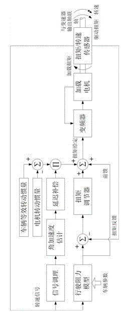
[0018] see figure 1 , the present invention provides a kind of method of electric simulation mechanical inertia, comprises steps as:

[0019] (1) Fix the transmission to be tested on the transmission test bench, start the control computer and the frequency converter, and input the parameters of the vehicle that matches the transmission to be tested into the control computer;

[0020] (2) The control computer detects the speed of the output shaft of the transmission, and calculates the torque to be loaded and the inertia to be simulated by the loading motor in the transmission test bench according to the parameters of the vehicle. The calculation ...


PUM


Abstract

The invention discloses a method for electrically simulating mechanical inertia. The method comprises the steps of: estimating an angular acceleration by applying Kalman filtering based on a measured angular speed; performing delay compensation on the estimated angular acceleration to obtain an exact real-time angular acceleration; and forming an electric inertia torque given value by the exact real-time angular acceleration based on the value of the simulated inertia, transmitting the electric inertia torque given value to a frequency converter, and controlling an electromagnetic torque of a loading motor by the frequency converter to realize electric simulation of the mechanical inertia. Through the way, the method for electrically simulating the mechanical inertia, provided by the invention, has the advantages of satisfying requirements of a speed changer test to the inertia simulation, simplifying mechanical structure of a speed changer test-bed, improving inertia simulation precision, realizing stepless adjustment of the inertia, removing level difference existing during the simulation of the inertia of a mechanical flywheel, guaranteeing credibility of the test, improving automatic degree of the speed changer test-bed and getting wide attention from car bench test equipment manufacturers.

Description

technical field [0001] The invention relates to the field of transmission bench test equipment, in particular to a method for electrically simulating mechanical inertia. Background technique [0002] The transmission is one of the most important components in the vehicle transmission system. Its performance is directly related to the power performance, fuel economy and comfort of the vehicle, and has an important impact on the improvement of the vehicle performance. Its performance, efficiency, reliability and Parameters such as durability cannot only rely on calculations, but must be confirmed by tests. At the same time, the rationality of transmission gears, bearing materials, structural design, manufacturing processes, loads, speeds, and lubrication conditions must also be verified through tests, so as to provide a solid foundation for the product. Design and quality evaluation provide a solid scientific basis. The bench test in the preliminary research and development o...

Claims


Application Information

Patent Timeline
Patent Type & Authority Applications(China)
IPC IPC(8): G01M13/02
Inventor 张为公王皖君林国余
Owner SOUTHEAST UNIV
Why Eureka
Try Eureka