Shifting register unit, grid electrode drive circuit and display device

A technology of a shift register and a reset unit, which is applied in the fields of gate drive circuits, display devices, and shift register units, can solve the problems of high noise, multiple outputs, and the reset unit cannot perform noise suppression, and achieves the effect of suppressing noise.

A technology of a shift register and a reset unit, which is applied in the fields of gate drive circuits, display devices, and shift register units, can solve the problems of high noise, multiple outputs, and the reset unit cannot perform noise suppression, and achieves the effect of suppressing noise.

CN102915698AActive Publication Date: 2013-02-06BOE TECH GRP CO LTD

Image

  • Shifting register unit, grid electrode drive circuit and display device
  • Shifting register unit, grid electrode drive circuit and display device
  • Shifting register unit, grid electrode drive circuit and display device

Examples


no. 1 example

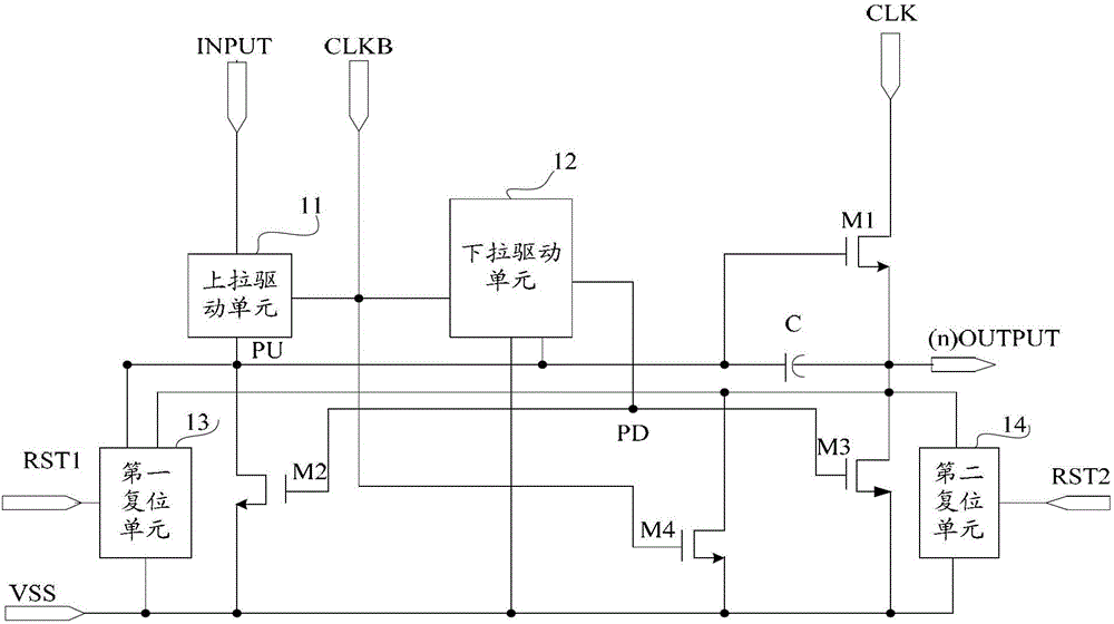
[0061] Such as figure 2 Said, the first embodiment of the shift register unit of the present invention comprises:

[0062] Output pull-up transistor M1, the gate of the output pull-up transistor M1 is connected to the pull-up node PU, the drain is connected to the first clock signal terminal CLK, and the source is connected to the output terminal (n) OUTPUT of the current stage;

[0063] The pull-up node pull-down transistor M2, the gate of the pull-up node pull-down transistor M2 is connected to the pull-down node PD, the drain is connected to the pull-up node PU, and the source is connected to the low-level output terminal VSS;

[0064] Output pull-down transistor M3, the gate of the output pull-down transistor M3 is connected to the pull-down node PD, the drain is connected to the output terminal of the current stage, and the source is connected to the low-level output terminal VSS;

[0065] Output transistor M4, the gate of the output transistor M4 is connected to the se...


PUM


Abstract

The invention provides a shifting register unit, a grid electrode drive circuit and a display device. The shifting register unit comprises an output up-pull transistor, an up-pull node down-pull transistor, an output down-pull transistor, an output transistor, a bootstrap capacitor, an up-pull drive unit, a down-pull drive unit, a first resetting unit and a second resetting unit, wherein the first resetting unit is respectively connected with a first resetting end, an up-pull node, a local-level output end and a low-level output end; the first resetting end is connected with the output end of a next-level shifting register unit; the second resetting unit is respectively connected with a second resetting end, a local-level output end and a low-level output end; and the second resetting end is connected with the output end of a Nth-level shifting register unit after being connected with a previous-level shifting register unit, and the N is an integer which is more than one. At least two resetting units are adopted to inhibit the noise between the first unit time after the current output and the Nth unit time.

Description

technical field [0001] The invention relates to the field of organic light-emitting display, in particular to a shift register unit, a gate drive circuit and a display device. Background technique [0002] The integrated gate shift register integrates the gate pulse output register on the panel, which saves IC and reduces the cost. There are many ways to realize the integrated gate shift register, which can contain different transistors and capacitors. The commonly used structures are 12T1C, 9T1C, 13T1C and so on. The realization of the shift pulse must at least include a set of clock signals, a pull-up transistor, a pull-down transistor and an output transistor. [0003] After the GOA (Gate Driver On Array, array substrate row drive) circuit is used for a period of time, due to the deterioration of the performance of the discharge thin film transistor, the discharge current decreases, and the output noise increases. This noise may be used as the next-level GOA unit circuit...

Claims


Application Information

Patent Timeline
06 Feb 2013
Publication
CN102915698A
IPC
G09G3/20; G09G3/32; G09G3/3266
Inventors
张玉婷