Quick connector

A connector, fast technology, applied in the direction of couplings, pipe joints, pipes/pipe joints/pipe fittings, etc., can solve the problem of high cost

Active Publication Date: 2015-03-18
SUMITOMO RIKO CO LTD
View PDF6 Cites 0 Cited by
  • Summary
  • Abstract
  • Description
  • Claims
  • Application Information

AI Technical Summary

Problems solved by technology

Although the above problems can be solved by high-precision manufacturing after adjusting the dimensions of each part, there is a problem that it must be manufactured with higher precision as miniaturization is pursued.
Also, the higher the accuracy, the higher the cost

Method used


Image

  • Quick connector
  • Quick connector
  • Quick connector

Examples


no. 1 approach

[0086] Overview of Quick Connectors

[0087] refer to Figure 1 ~ Figure 3 The outline of the quick connector 1 according to this embodiment will be described. Such as figure 1 As shown, the quick connector 1 is used to form, for example, gasoline fuel piping of an automobile. That is, the quick connector 1 forms a flow path through which, for example, fuel flows. One end side of the quick connector 1 ( figure 1 , figure 2 on the left side) is connected with the resin tube (not shown), the tube body 3 (such as Figure 23 shown) is inserted into the other end side of the quick connector 1 and connected with the other end side. That is, the quick connector 1 performs piping connection of the pipe body 3 and the resin pipe, and allows gasoline fuel to flow. The tube body 3 is formed in a cylindrical shape, and has an annular protrusion 3a (such as Figure 23 shown). The quick connector 1 includes a first housing 10 , a second housing 30 , a checker 50 , a collar 70 an...

no. 2 approach

[0149] Next, the quick connector of the second embodiment will be described. The second housing and the checker of the quick connector of the second embodiment are different from the quick connector of the first embodiment. In addition, the mode in the locked confirmation state and when moving from the locked confirmed state to the released state is different from that of the first embodiment. The difference will be described below. In addition, the same code|symbol is attached|subjected to the same structure as 1st Embodiment, and description is abbreviate|omitted.

[0150] Detailed structure of the second shell

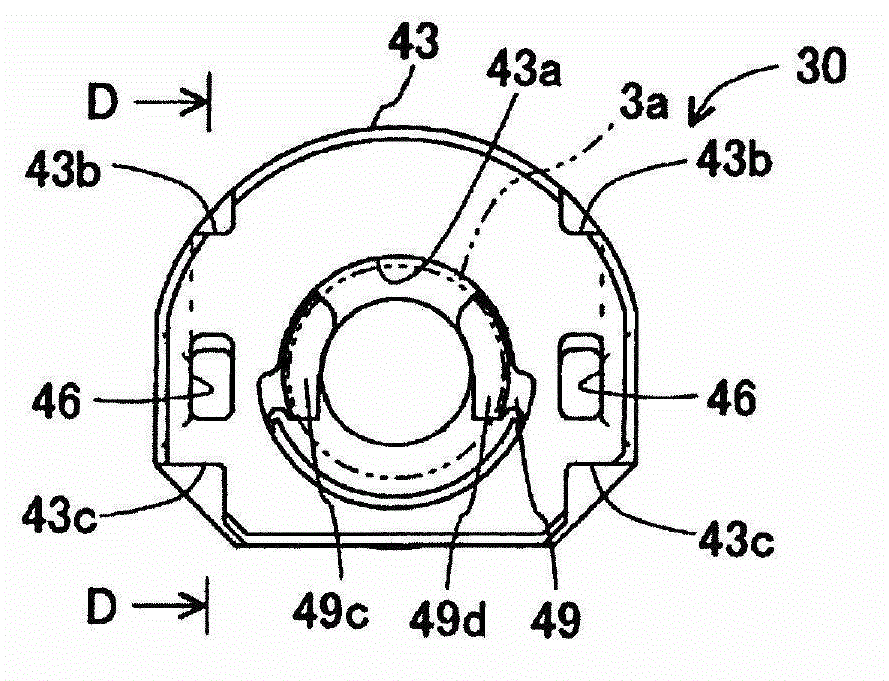
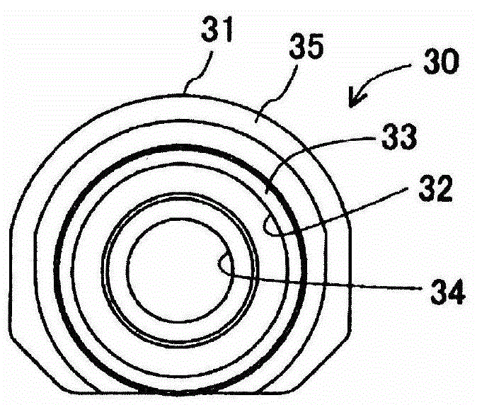
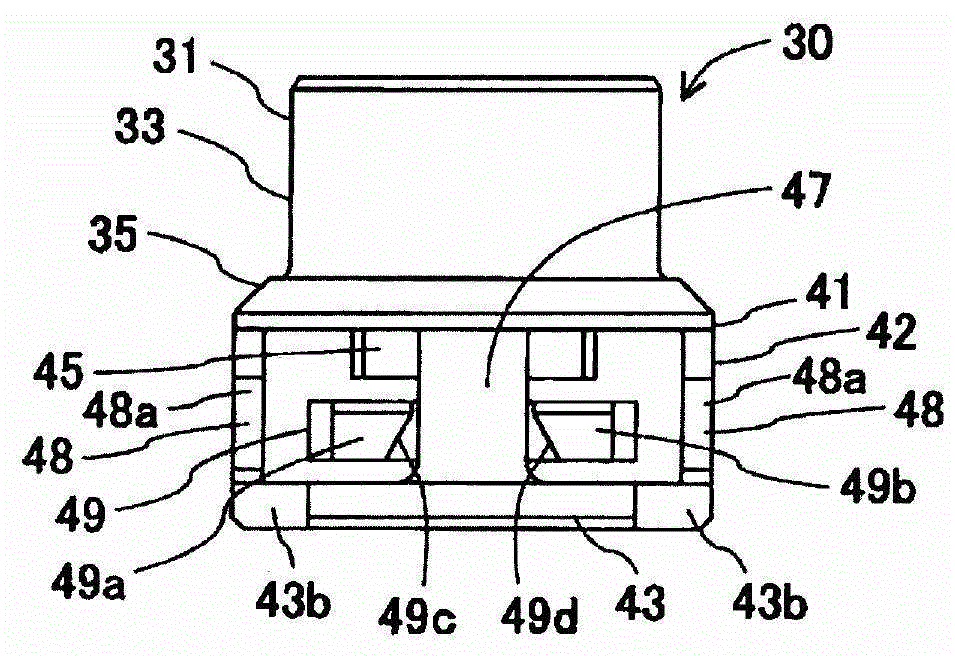
[0151] refer to Figure 38 ~ Figure 46 The detailed structure of the second housing 130 will be described. The second housing 130 includes a housing body part 131 and a holder part 141 . In addition, since the case main body portion 131 and the holder portion 141 are integrally formed, there is no strict boundary, but here, the Figure 38 The axis direction ...


PUM


Abstract

To provide a quick connector capable of surely confirming that a pipe body is engaged by a retainer when an elastically-deformable claw of the retainer and an elastically-deformable claw of a checker are adjacently arranged in an axial direction. Checker-axis direction elastically-deformable claws 52 and 52 have distal-end sides formed flexibly deformable in the axial direction, maintain a state of being engaged by a second engagement portion 46 of a retainer body 42 by having deflective deformation regulated by a retainer diameter-expanding elastically-deformable claw 49 in a state in which the retainer diameter-expanding elastically-deformable claw 49 is expanded diametrically, and regulate sliding from a first position with respect to the retainer body 42 toward a set radial direction by being engaged by the second engagement portion 46 of the retainer body 42. The checker-axis direction elastically-deformable claws 52 and 52 become releasable from engagement with the second engagement portion 46 of the retainer body 42 in a state in which the retainer diameter-expanding elastically-deformable claw 49 has restored its original shape, and thereby become slidable with respect to the retainer body 42 from the first position toward the second position in the set radial direction.

Description

technical field [0001] The invention relates to a quick connector. Background technique [0002] Examples of quick connectors include those disclosed in JP-A-2005-282762 (Patent Document 1) and JP-A-2007-278508 (Patent Document 2). These documents describe quick connectors that have a checker that confirms whether or not the tube body is securely locked to the holder. [0003] The operation performed until the locking is confirmed by the checker is as follows. When the tubular body is inserted into the retainer, the diameter of the elastically deformable claw of the retainer is enlarged by the annular protrusion of the tubular body. Then, when the annular protrusion of the tubular body passes the position of the elastically deformable claw of the holder, the shape of the elastically deformable claw is restored, and the annular protrusion of the tubular body is locked with the elastically deformable claw of the retainer. On the other hand, the diameter of the elastically d...

Claims


Application Information

Patent Timeline
Patent Type & Authority Patents(China)
IPC IPC(8): F16L37/12
CPCF16L37/088F16L37/133F16L2201/10F16L37/144F16L37/0985F16L2201/20F16L37/0885
Inventor 山田裕志坂崎一茂柴田孝广池上亮寺山尚志
Owner SUMITOMO RIKO CO LTD
Why Eureka
Try Eureka