Supercharge Your Innovation With Domain-Expert AI Agents!

Liquid crystal bottle cap

A liquid crystal and capping technology, which is applied in the field of liquid crystal bottle caps, can solve the problem that the supply tube 56 cannot be inserted correctly.

Active Publication Date: 2013-02-13
TOP ENG CO LTD
View PDF2 Cites 0 Cited by
  • Summary
  • Abstract
  • Description
  • Claims
  • Application Information

AI Technical Summary

Problems solved by technology

Thus, if the supply hole 46 does not face the supply tube 56 of the liquid crystal supply unit 50 due to a change in the positioning of the supply hole 46, the supply tube 56 cannot be properly inserted into the liquid crystal vial head 40, for example, the supply tube 56 may come into contact with the liquid crystal vial seal. The outer wall of the head 40 collides so that it is impossible to supply the liquid crystal into the liquid crystal bottle 26

Method used


Image

  • Liquid crystal bottle cap
  • Liquid crystal bottle cap
  • Liquid crystal bottle cap

Examples


Embodiment Construction

[0038] Preferred embodiments of the present invention will be described in detail below with reference to the accompanying drawings. In the following description, the front side of the coating head unit, that is, the side where the liquid crystal supply unit is disposed is referred to as a "front" side, and the opposite side is referred to as a "rear" side.

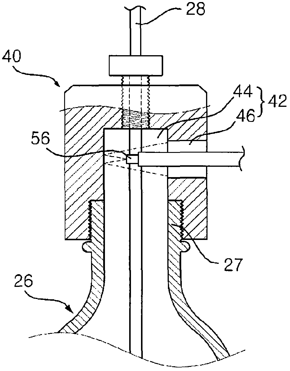
[0039] Figure 4 is a side view showing the liquid crystal bottle cap coupled to the liquid crystal bottle and the guide member according to the first embodiment of the present invention. Figure 5 is to show the Figure 4 An exploded perspective view of the structure in which the liquid crystal bottle head is coupled to the liquid crystal bottle and the guide member. Figure 6 yes Figure 5 vertical section view of . Figure 7 is a vertical sectional view showing the use of the liquid crystal bottle cap coupled to the liquid crystal bottle and the guide member according to the first embodiment of the present inventio...


PUM


Abstract

The article discloses a liquid crystal bottle cap for connection of the liquid crystal bottle arranged in a LC coating machine. The liquid crystal bottle cap comprises a positioning mounting support, a funnel member, and a liquid crystal guiding member. The support is connected with the guiding member, the support is provided with a connecting hole connected to a neck portion of the liquid crystal bottle, a funnel member plug hole is connected with the connecting hole, and a first supply hole is connected with the funnel member plug hole. The funnel member is inserted into the funnel member plug hole, and the funnel member is provided with a flow hole formed from a top surface of the funnel member to a bottom surface, and a second supply hole is provided to connect the first supply hole with the flow hole. The liquid crystal guiding member is inserted into the flow hole, the guiding member is provided with a slope, and the slope leans downwards corresponding to a direction in which the liquid crystal is supplied to the flow hole.

Description

technical field [0001] The present invention generally relates to a liquid crystal bottle cap, and more particularly relates to a liquid crystal bottle cap which is connected with a liquid crystal bottle arranged in a LC (liquid crystal, liquid crystal) coating machine and has a supply hole, through which the liquid crystal The supply hole supplies to the liquid crystal bottle. Background technique [0002] In general, a liquid crystal coating process in a method of manufacturing an LCD includes directly coating a liquid crystal on a glass panel, and then applying pressure by bonding another glass panel to the aforementioned glass panel to uniformly coat the coated liquid crystal. onto the entire area of ​​the glass panel, thereby forming a liquid crystal layer. LC coaters are typically used to coat liquid crystals onto glass panels. [0003] figure 1 is a schematic side view showing an example of an LC coater having a liquid crystal supply unit. figure 2 is showing fi...

Claims


Application Information

Patent Timeline
IPC IPC(8): B05C11/115
CPCG02F1/1303G02F1/1341
Inventor 金周瀚
Owner TOP ENG CO LTD
Features
  • R&D
  • Intellectual Property
  • Life Sciences
  • Materials
  • Tech Scout
  • Unparalleled Data Quality
  • Higher Quality Content
  • 60% Fewer Hallucinations
Learn More