Hydraulic control valve unit for rotating-vane type steering engine

A hydraulic control valve and rotary vane technology, which is applied in the direction of rudder steering, mechanical equipment, servo motor components, etc., can solve the problems of large calorific value and large volume of rotary vane steering gear, and achieve small pressure loss and low valve pressure. Set of compact, wide-ranging effects

Active Publication Date: 2013-02-13
WUHAN MARINE MACHINERY PLANT
View PDF5 Cites 11 Cited by
  • Summary
  • Abstract
  • Description
  • Claims
  • Application Information

AI Technical Summary

Problems solved by technology

[0006] In order to solve the problem that the hydraulic system generates a large amount of heat in the prior art, resulting in a large volume of the rotary vane steering gear, the embodiment of the present invention provides a hydraulic control valve group for the rotary vane steering gear

Method used


Image

  • Hydraulic control valve unit for rotating-vane type steering engine
  • Hydraulic control valve unit for rotating-vane type steering engine

Examples


Embodiment 1

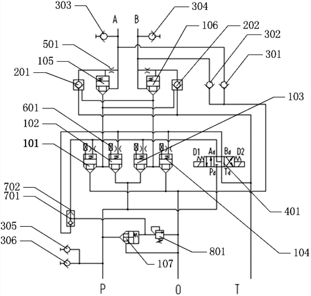
[0028] Such as figure 1 As shown, the embodiment of the present invention provides a hydraulic control valve group for a rotary vane steering gear, the valve group includes: electromagnetic reversing valve 401, shuttle valve 701, pilot relief valve 801 and 7 cartridge valves , the oil inlet P of the valve group communicates with the first oil port of the seventh cartridge valve 107 and the first oil inlet Pd of the electromagnetic reversing valve 401 respectively, and the oil outlet of the seventh cartridge valve 107 communicates with the valve The oil outlet O of the group is connected, the oil control port of the seventh cartridge valve 107 is connected with the oil inlet port of the pilot relief valve 801, the oil outlet of the pilot relief valve 801 is connected with the oil outlet O, and the seventh cartridge The installed valve 107 and the pilot relief valve 801 cooperate with the electromagnetic reversing valve 401 to regulate and unload the hydraulic system.

[0029] ...


PUM


Abstract

The invention discloses a hydraulic control valve unit for a rotating-vane type steering engine, belonging to the field of hydraulic control valve units. The hydraulic control valve unit comprises an electromagnetic reversing vale, a shuttle valve, a pilot-operated relief valve, a first cartridge valve, a second cartridge valve, a third cartridge valve, a fourth cartridge valve, a fifth cartridge valve, a sixth cartridge valve and a seventh cartridge valve; an oil inlet of the hydraulic control valve unit is communicated with a first oil inlet of the seventh cartridge valve and a first oil inlet of the electromagnetic reversing vale; a second oil inlet of the seventh cartridge valve is communicated with the oil outlet of the hydraulic control valve unit; an oil control port of the seventh cartridge valve is communicated with an oil inlet and an oil outlet of the pilot-operated relief valve; and the oil outlet of the pilot-operated relief valve is communicated with the oil outlet of the hydraulic control valve unit. The heating of a hydraulic system is reduced, thus the size of an oil tank of a hydraulic pump station is reduced, and the space in a ship is saved.

Description

technical field [0001] The invention relates to the field of hydraulic control valve groups, in particular to a hydraulic control valve group for a rotary vane steering gear. Background technique [0002] Rotary vane steering gear is a new type of steering gear widely used in various ships in the world. Its working principle is similar to that of a two-way swing blade motor. The rotation of the rotor is the output of the device. The rotor and the rudder stock are connected by interference or other means. The rotation of the rotor drives the rotation of the rudder stock, thereby realizing the motion control of the rudder blades. . [0003] The rotary vane hydraulic steering gear controls the rotation of the rotor through the hydraulic system. The hydraulic system uses multiple slide valves, internal control reversing valves and other valves to cooperate with other components in the hydraulic system to provide sufficient hydraulic energy to the steering gear. During the work...

Claims


Application Information

Patent Timeline
Patent Type & Authority Applications(China)
IPC IPC(8): B63H25/30F15B13/02
Inventor 胡红斌胡志忠经鹏飞况念杨竣张文斌
Owner WUHAN MARINE MACHINERY PLANT
Why Eureka
Try Eureka