
Two-way memory alloy flow control device

A technology of flow control device and memory alloy, which is applied in transportation and packaging, air handling equipment, aircraft parts, etc. It can solve problems affecting the stable operation of working equipment, difficulty in starting working equipment, and fluctuations in ambient temperature, etc., and achieves light weight and structure. Simple, vibration-free effect

Inactive Publication Date: 2013-02-13
XIAN AIRCRAFT DESIGN INST OF AVIATION IND OF CHINA
View PDF4 Cites 8 Cited by
  • Summary
  • Abstract
  • Description
  • Claims
  • Application Information

AI Technical Summary

Problems solved by technology

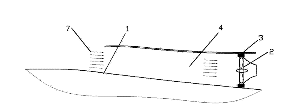
[0002] like figure 1 Shown is an ambient temperature control device for working equipment on an existing aircraft, which is composed of an air inlet and working equipment. The working state of the working equipment works best when the ambient temperature is 30-45°C, and 40°C is taken as its critical working temperature. Under normal circumstances, it is necessary to adjust the ambient temperature of the working equipment with appropriate cooling air volume. When the ambient temperature is higher than the critical temperature, the working equipment will not work normally. When the ambient temperature is much lower than the critical temperature, the working equipment will be difficult to start, but the working equipment As the speed and altitude of the aircraft continue to change, the flow and temperature of the cooling air also fluctuate violently, causing large fluctuations in the ambient temperature and seriously affecting the stable operation of the working equipment. The only solution at present is to continuously improve the heat preservation or heat dissipation capacity of the equipment. To adapt to the violent fluctuations in temperature, it also brings higher requirements for materials, process level, and assembly quality, and the cost increases a lot

Method used


Image

  • Two-way memory alloy flow control device
  • Two-way memory alloy flow control device
  • Two-way memory alloy flow control device

Examples


Embodiment Construction

[0011] The present invention will be described in detail below in conjunction with the accompanying drawings.

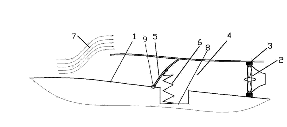
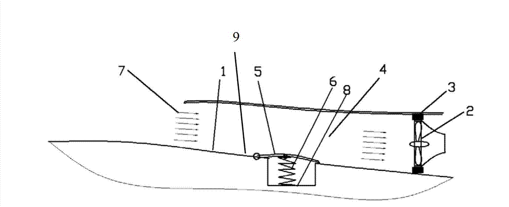
[0012] 1. The device includes a cooling air passage 4 installed on the outside of the aircraft body 1, working equipment 2 installed at the rear end of the cooling air passage 4, a shock-absorbing sealing bush 3, a flow control door 5 installed on the airframe, and a two-way memory alloy spring 6. Mounting groove 8,

[0013] The cooling air channel 4 described in 2 is a common general air intake on existing aircraft, and the active air device 2 is arranged at the rear end of the cooling air channel 4, and the flexible installation bushing 3 is connected around the air device 2, which can slow down With the vibration of the wind equipment, the outer side of the installation bush is closely connected with the inner wall of the air inlet.

[0014] 3. There is a memory alloy installation groove 8 on the aircraft body. The installation groove 8 is located at the far end ...


PUM


Abstract

The invention belongs to the technical field of airplane design and relates to a two-way memory alloy flow control device which is used for controlling the ambient temperature of airplane working equipment. The device comprises a cooling air channel, a piece of working equipment and a damping sealing liner, wherein the cooling air channel is installed at the outer side of an airplane body; the working equipment and the damping sealing liner are installed at the rear end of the cooling air channel; a memory alloy installing groove is formed in the airplane body; the installing groove is positioned at a remote end of the working equipment inside the cooling air channel; a spiral spring is installed inside the installing groove; the spiral spring is made of a two-way memory alloy; the outer end of the spiral spring is hinged with a control air door; one end of the control air door is connected with the airplane body structure through a hinge; the hinge is positioned at the front end of the installing groove; when the cooling air channel is opened through the control air door, the installing groove is sealed; and when the cooling air channel is closed through the control air door, the gap between the inner walls of the control air door and the cooling air channel is not less than 5mm. The flow of the cold air is controlled by using the two-way phase transition feature of the two-way memory alloy in critical temperature, so that the problem that the airplane working equipment does not work stably is solved.

Description

technical field [0001] The invention belongs to the technical field of aircraft design, relates to a two-way memory alloy flow control device used for ambient temperature control of aircraft working equipment, and is an improvement on the prior art. Background technique [0002] Such as figure 1 Shown is an ambient temperature control device for working equipment on an existing aircraft, which is composed of an air inlet and working equipment. The working state of the working equipment works best when the ambient temperature is 30-45°C, and 40°C is taken as its critical working temperature. Under normal circumstances, it is necessary to adjust the ambient temperature of the working equipment with appropriate cooling air volume. When the ambient temperature is higher than the critical temperature, the working equipment will not work normally. When the ambient temperature is much lower than the critical temperature, the working equipment will be difficult to start, but the wor...

Claims


Application Information

Patent Timeline
Patent Type & Authority Applications(China)
IPC IPC(8): B64D13/00
Inventor 王勇杨毅党育辉
Owner XIAN AIRCRAFT DESIGN INST OF AVIATION IND OF CHINA
Learn More