

Interstage cooling system of water-saving compressor
A compressor stage, cooling system technology, applied in mechanical equipment, machinery/engine, liquid variable capacity machinery, etc., can solve problems such as large water consumption, and achieve the effect of high heat exchange capacity
- Summary
- Abstract
- Description
- Claims
- Application Information
AI Technical Summary
Problems solved by technology
Method used
Image

Examples
Embodiment 1
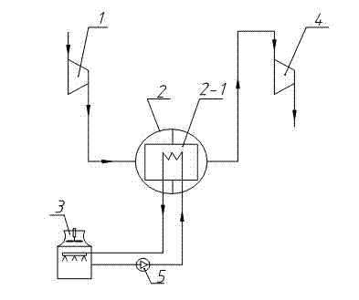
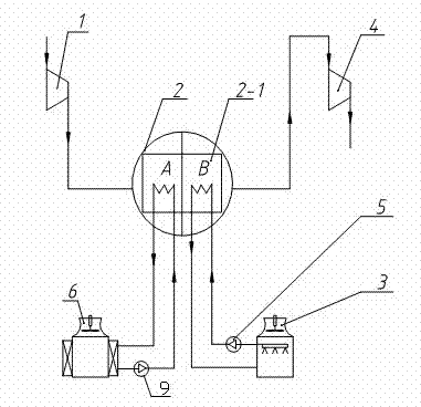
[0030] see figure 2 , figure 2 It is a schematic diagram of Embodiment 1 for implementing the present invention. Depend on figure 2 It can be seen that the water-saving compressor interstage cooling system of the present invention is composed of a compressor front stage 1, an interstage cooler 2, a compressor rear stage 4, a first cooling water pump 5, and a water cooling tower 3. Cooling coil 2-1 is arranged in interstage cooler 2, and figure 1 The difference of the prior art shown is that in this embodiment 1, the cooling coil 2-1 in the interstage cooler 2 is divided into two parts, the high temperature zone A and the low temperature zone B, and an air cooling tower 6 is added to the system With the corresponding second cooling water pump 9, the cooling water pipeline in the high temperature zone A is connected with the air cooling tower 6, and the cooling water pipeline in the low temperature zone B is connected with the water cooling tower; the cooling water in the ...
Embodiment 2
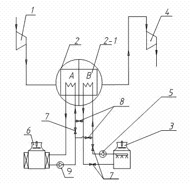
[0033] see image 3 , Embodiment 2 is on the basis of Embodiment 1, the water outlet pipe of the second cooling water pump 9 corresponding to the air cooling tower 6 is connected with the water inlet pipe of the low temperature zone B of the cooling coil 2-1, and the water inlet pipe of the low temperature zone B is connected. The outlet pipe is connected to the water inlet pipe of the high temperature zone A, and the first switch valve 7 (3 in total) and the second switch valve 8 (2 pieces) are added, and the first switch valve 7 is opened and the second switch valve 8 is closed to make the high temperature zone The cooling water in A and low temperature zone B is cooled in the air cooling tower 6 and in the water cooling tower 3 respectively, or close the first switch valve 7 and open the second switch valve 8 to make the cooling water in the low temperature zone B and high temperature zone A connected in series The way is to cool in the air cooling tower 6, first enter the ...
Embodiment 3
[0035] see Figure 4 , Embodiment 3 is on the basis of Embodiment 1, the return pipe of the air cooling tower 6 and the outlet pipe of the corresponding second cooling water pump 9 are connected with the outlet pipe and the inlet pipe of the low-temperature zone B of the cooling coil 2-1 respectively. Connect, and add the first switching valve 7 (2 in total) and the second switching valve 8 (2) in the system pipeline, open the first switching valve 7 and close the second switching valve 8 to make the high temperature zone A and the low temperature zone The cooling water of B is cooled in the air cooling tower 6 and the water cooling tower 3 respectively, or the first switching valve 7 is closed and the second switching valve 8 is opened to make the cooling water in the low temperature zone B and the high temperature zone A cool in the air in parallel. Cooling in column 6.
PUM
 Abstract
Description
Claims
Application Information