
Crankshaft provided with main journal and rod journal

A connecting rod journal and crankshaft technology, applied in the crankshaft field, can solve problems such as high manufacturing costs, achieve the effects of reducing pressure concentration, reducing weight and risk of cracks, and reducing stress on parts

Inactive Publication Date: 2013-02-13
FORD GLOBAL TECH LLC
View PDF6 Cites 2 Cited by
  • Summary
  • Abstract
  • Description
  • Claims
  • Application Information

AI Technical Summary

Problems solved by technology

The support device and the inwardly expanding vias result in a relatively high manufacturing cost

Method used


Image

  • Crankshaft provided with main journal and rod journal

Examples


Embodiment Construction

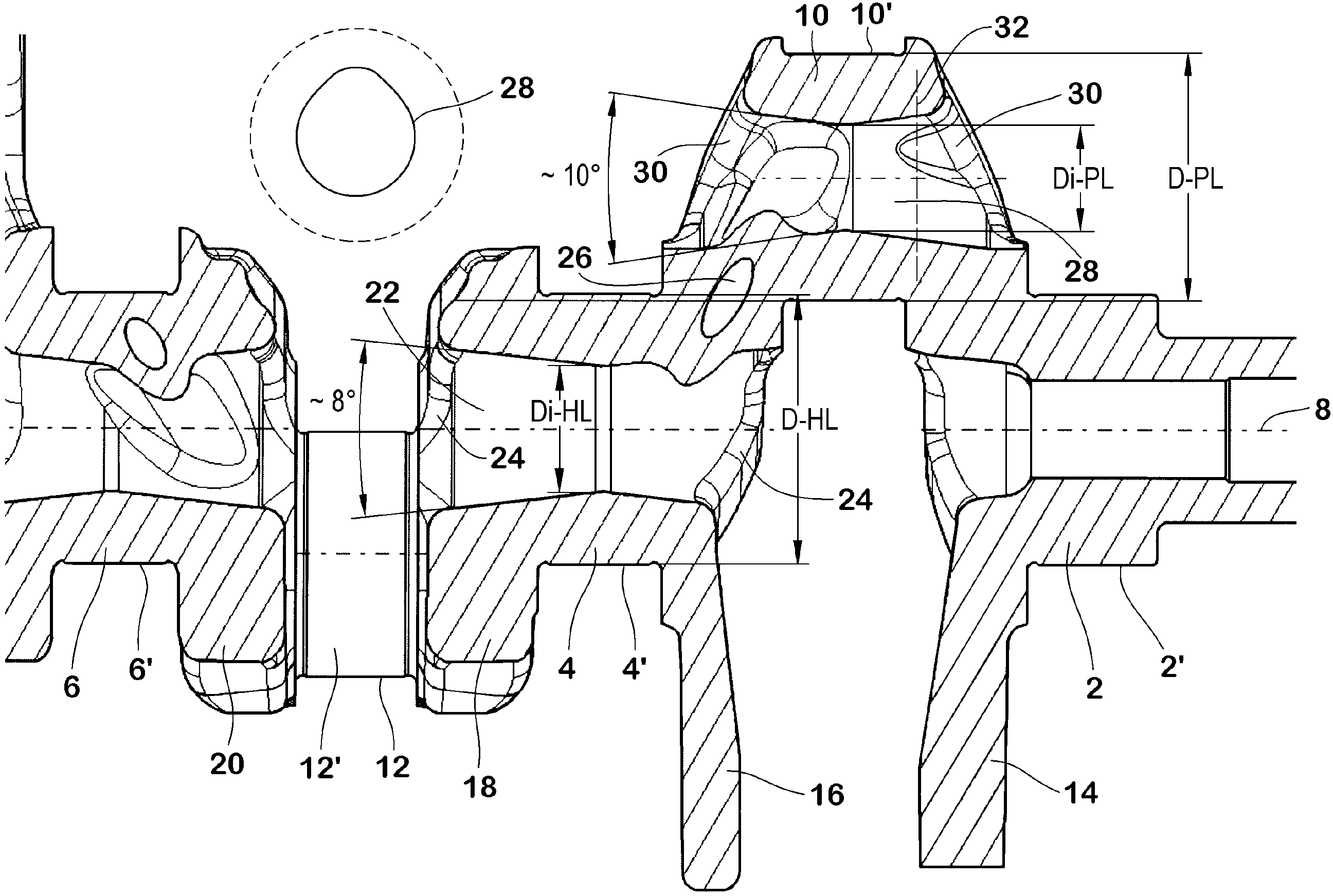
[0017] The crankshaft shown contains main journals 2, 4, 6... which are arranged axially at equal distances along the center axis 8 and which each have a cylindrical main bearing surface 2', 4' on their outer sides , 6'....

[0018] Between two adjacent main journals 2 , 4 , 6 . . . there are respectively connecting rod journals 10 , 12 . The connecting rod bearing surfaces 10', 12'.

[0019] Each connecting rod journal 10, 12 is connected to the adjacent main journal 2, 4, 6... by means of a crank arm 14, 16, 18, 20....

[0020] Only the axial section of the crankshaft containing the main journal 4 , the pin pin 10 and the associated crank arms 14 , 16 and 18 will be described in detail below. The other main and pin journals of the crankshaft are of the same or similar design.

[0021] The main journal 4 has an axial through-hole 22 which, starting from its narrowest point, widens conically both in the direction of its outlet to the crank arm 16 and in the direction of its...


PUM


Abstract

The invention relates to a crankshaft used for an internal combustion engine, the crankshaft is provided with at least two main journals (2, 4) and at least one rod journal (10), the crankshaft is connected with the adjacent main journal (4) through crank arms (14, 16), and the main journal (4) and the rod journal (10) are respectively provided with axial through holes (22, 28). The through holes (22, 28) in the main journals (2, 4) or the rod journal (10) extend in a cone shape towards outlets in the crank arms (14, 16).

Description

technical field [0001] The invention relates to a crankshaft for an internal combustion engine according to the preamble of claim 1 , which crankshaft has a hollow journal. Background technique [0002] Such hollow journals in crankshafts are known in principle from the prior art. This should result in a reduction in weight. However, due to the stress concentration in such crankshafts on the ends of the main and connecting rod journals, there is a risk of cracks forming, and to a higher degree than with solid crankshafts. [0003] Such a crankshaft is known from DE 38 37 292 A1, in which the above-mentioned danger is counteracted by a support means which is mounted in the crank arm (Kurbvelwangen) in the range of the main journal and the connecting rod journal, and which is mounted on the crankshaft A prestress is created in the material of the arm. In such crankshafts, the through bores in the main and pin journals narrow towards their outlets in the crank arms. The sup...

Claims


Application Information

Patent Timeline
IPC IPC(8): F16C3/06
CPCF16C2360/22F16C3/08F16C3/06F16C2220/02F16C2240/30F16C2240/70
Inventor B·斯坦纳E·韦斯M·克拉尔
Owner FORD GLOBAL TECH LLC
Learn More