
A backlight module

A technology of backlight module and back cover, which is applied in the direction of light source, electric light source, light source fixing, etc., can solve the problems of increasing the cost of liquid crystal display, widening and reducing the overall thickness of liquid crystal display, and achieving the goal of reducing thickness, height and cost Effect

Inactive Publication Date: 2013-02-13
AU OPTRONICS CORP
View PDF7 Cites 1 Cited by
  • Summary
  • Abstract
  • Description
  • Claims
  • Application Information

AI Technical Summary

Problems solved by technology

Generally, the direct type backlight module uses multiple LEDs on the substrate to directly project the light source to the position of the diffuser plate, and a light-mixing space with a visible light-emitting area is formed between the substrate and the diffuser plate. The position of each LED on the substrate , the projected range of each LED must be in line with the uniform distribution on the area of ​​the diffuser plate, so generally the width of the light mixing space will be increased and widened to make the LED projected distance longer and the maximum range of light source effect, obtained The effect of reducing the number of LEDs and projecting the widest range of effects on the diffuser plate, however, also results in a wider overall thickness of the LCD
[0003] Therefore, in order to make the liquid crystal display thinner, the width of the light mixing space must be relatively reduced and shortened. Generally, more LEDs are installed, and multiple LEDs are densely distributed and projected on the area and range of the diffuser plate. However, the cost of the liquid crystal display is increased relatively. Therefore, how to solve these problems is an urgent problem for the relevant industry in the technical field.

Method used


Image

  • A backlight module
  • A backlight module
  • A backlight module

Examples


Embodiment Construction

[0051] Below in conjunction with accompanying drawing, structural principle and working principle of the present invention are specifically described:

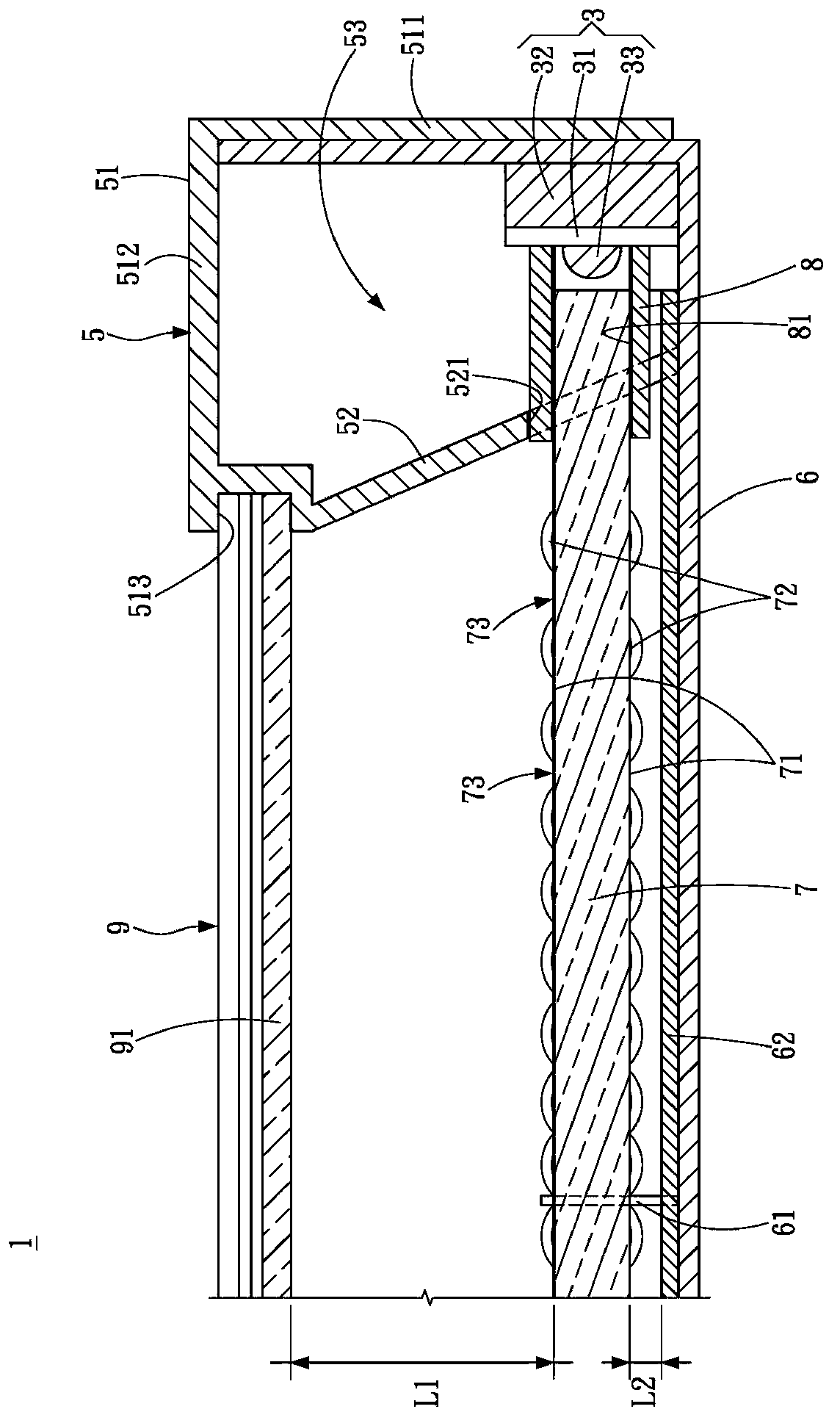
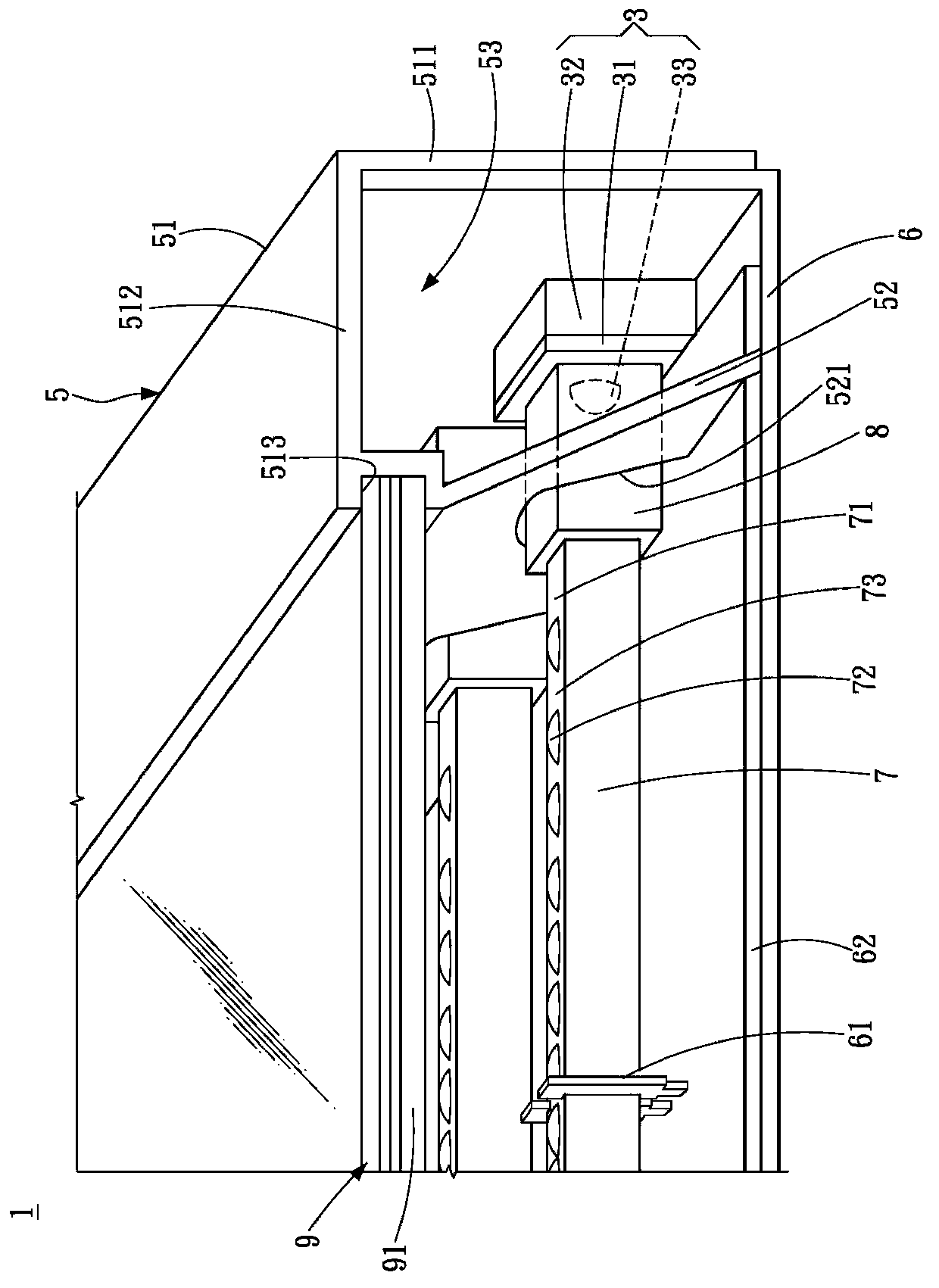
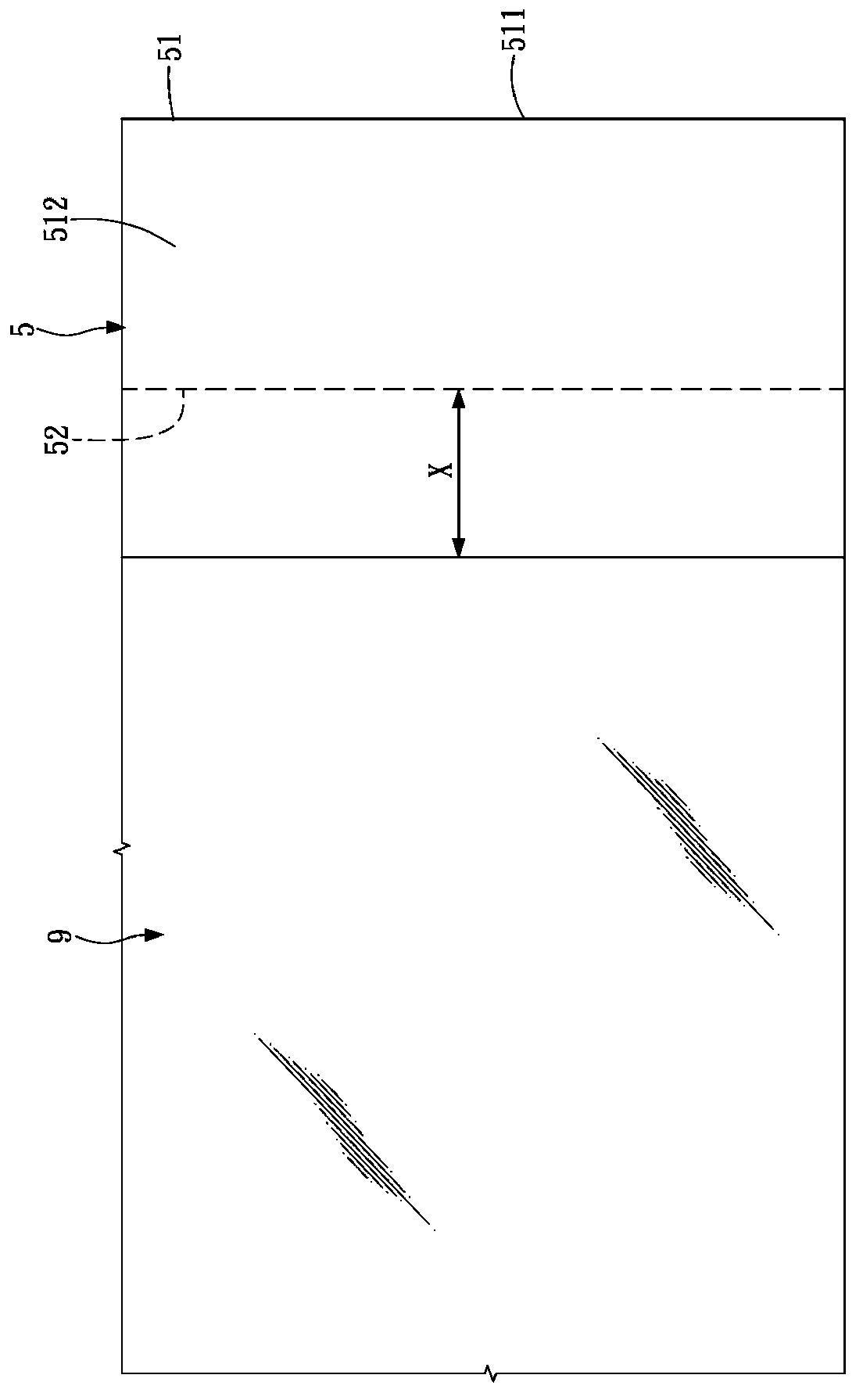
[0052] see figure 1 , figure 2 and image 3 , the first embodiment of the present invention. figure 1 is a partial cross-sectional schematic diagram, figure 2 is a schematic diagram of the local appearance, image 3 It is a partial top view schematic diagram.

[0053] Such as figure 1 and figure 2 As shown, the backlight module 1 in the first embodiment of the present invention includes: a plurality of light source modules 3 , a frame 5 and a plurality of light guide rods 7 .

[0054] The light source module 3 can be mainly composed of a substrate 31, a support seat 32 and a light emitting element 33, wherein the light emitting element 33 is welded on the substrate 31, the substrate 31 is positioned on the support seat 32, and the support seat 32 can be selected to have a high thermal conductivity The heat dissipati...


PUM


Abstract

A backlight module comprises a plurality of light emitting elements, the frame and a plurality of the light guide rod; wherein the framework includes a main body portion and the reflection portion, the main body portion and the reflection portion is formed between the accommodating space to a plurality of the light emitting element, a reflective portionconnected to the main body portion, and extending obliquely toward the plurality of light emitting elements; plurality of the light guide rod is located in one end side of the plurality of light-emitting element, and the reflection portion facing the plurality of light guide rods.

Description

technical field [0001] The invention relates to a backlight module, in particular to a backlight module of a display panel. Background technique [0002] Ordinary liquid crystal displays mainly use liquid crystal panels (LCD panels) for display. Since the LCD panel is a non-self-illuminating display panel, a backlight module must be used to supply a light source with sufficient brightness and uniform distribution to make the LCD panel display images normally. Generally, the direct type backlight module uses multiple LEDs on the substrate to directly project the light source to the position of the diffuser plate, and a light-mixing space with a visible light-emitting area is formed between the substrate and the diffuser plate. The position of each LED on the substrate , the projected range of each LED must be in line with the uniform distribution on the area of ​​the diffuser plate, so generally the width of the light mixing space will be increased and widened to make the LED...

Claims


Application Information

Patent Timeline
Patent Type & Authority Applications(China)
IPC IPC(8): F21S8/00F21V17/00F21V19/00F21Y101/02F21Y115/10
Inventor 陈明伦谢坤宏
Owner AU OPTRONICS CORP
Learn More