Sag rod for measurement

A sag and rod body technology is applied in the field of sag observation tools for high and low voltage lines, and achieves the effects of simple structure, easy portability and use, and extended length.

Active Publication Date: 2013-02-13
DEYANG POWER SUPPLY COMPANY STATE GRID SICHUAN ELECTRIC POWER +1
View PDF5 Cites 11 Cited by
  • Summary
  • Abstract
  • Description
  • Claims
  • Application Information

AI Technical Summary

Problems solved by technology

[0002]At present, there is no clear requirement for sag when the overhead lines of the distribution network are newly built, and the sag error is relatively large. Disconnection, too loose winding during construction in winter will easily cause too much sag in summer, and in thunderstorm season, adjacent wires will be entangled due to large sag, which will lead to safety accidents in distribution lines
In addition, when wiring, the sag of the distribution line is basically determined by experience, which is likely to cause unsightly workmanship

Method used


Image

  • Sag rod for measurement
  • Sag rod for measurement
  • Sag rod for measurement

Examples


Embodiment 1

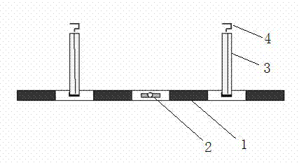
[0020] as attached figure 1 As shown, the measuring sag rod of the present embodiment comprises a sag rod 1, and the sag rod 1 is a PVC pipe with a red and white warning mark, and a spirit level 2 is installed in the middle of the sag rod 1, Both sides of the sag rod 1 are symmetrically installed with retractable tape measures 3 , the ends of the retractable tape measure 3 are connected with hooks 4 , and the two ends of the sag rod 1 are telescopic rod bodies.

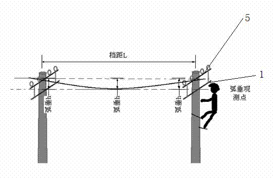
[0021] as attached figure 2 As shown, in the process of stringing, when the sag rod for measurement of this embodiment is used to observe the sag of the conductor, the method of observation in the file is adopted. Select two adjacent base poles to install the upper sag poles 1 respectively. When installing, hang the hook on the end of the retractable tape 3 on the pole beam 5, and pull the retractable tape 3 according to the weather and wire type during construction. Extend to the distance that the wire needs to s...

Embodiment 2

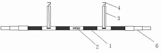
[0024] The sag rod for measurement in this embodiment is the same as that in Embodiment 1, except that the two ends of the sag rod in this embodiment are also connected with telescopic rods 6, and the telescopic rods 6 are multi-section hollow rods that are nested and connected in sequence. When the multi-section hollow rods are stretched, the two hollow rods are connected sequentially. When the multi-section hollow rods are retracted, they are nested in the outermost hollow rods. By connecting the telescopic rods 6 at both ends of the arc sag rods, the arc The length of the vertical rod is convenient to use when the sag value of several parallel lines needs to be observed at the same time, and the distance between the lines is relatively large.


PUM


Abstract

The invention relates to high-low pressure line conductor sag observation tools, in particular to a sag rod for measurement. The sag rod for the measurement comprises a sag rob body, a leveling instrument is arranged in the middle of the sag rob body, extensible flexible tapes are symmetrically arranged on two sides of the sag rob body, and end tips of the extensible flexible tapes are connected with pothooks. The sag rod for the measurement is simple in structure, convenient to carry and use and suitable for use for electric power circuit construction workers. The extensible flexible tapes are provided with ruling, sag values can be adjusted freely, and the sag rod for the measurement can judge whether circuit sags are qualified or not quickly and accurately. The sag rob body is provided with marked ruling and can be used as a measurement tool conveniently. Due to the fact that two ends of the sag rob body are connected with expansion rods, the length of the sag rob body can be lengthened and application range is wide.

Description

technical field [0001] The invention relates to a high-voltage and low-voltage line wire sag observation tool, in particular to a sag rod for measurement. Background technique [0002] At present, there is no clear requirement for sag when the overhead lines of the distribution network are newly built, and the sag error is relatively large. If the line is too tight in summer construction, it will easily cause the line to break due to heat expansion and contraction in winter, and if the line is too loose in winter construction, it will easily cause sag in summer. If it is too large, the adjacent conductors will be entangled together due to the large sag in the windy thunderstorm season, resulting in a safety accident on the distribution line. In addition, when wiring, the sag of the distribution line is basically judged by experience, which is likely to cause unsightly workmanship. Contents of the invention [0003] The object of the present invention is to overcome the...

Claims


Application Information

Patent Timeline
Patent Type & Authority Applications(China)
IPC IPC(8): G01B5/02
Inventor 马云倪忠孝
Owner DEYANG POWER SUPPLY COMPANY STATE GRID SICHUAN ELECTRIC POWER
Why Eureka
Try Eureka