Tension testing device of traction belt

A tensile test and traction belt technology, which is applied in the direction of applying stable tension/pressure to test the strength of materials, can solve the problems of inconvenience, low intelligence, and low level of tensile testing, and achieves convenient testing, safe and reliable use. , the effect of simple structure

Inactive Publication Date: 2013-02-13
安徽恒索带业有限公司
View PDF3 Cites 4 Cited by
  • Summary
  • Abstract
  • Description
  • Claims
  • Application Information

AI Technical Summary

Problems solved by technology

However, the structure of the traditional test device is too simple, the degree of intelligence is low, and the tension status cannot be displayed in time, and the level of the tension test is very low, so it is very inconvenient to use

Method used


Image

  • Tension testing device of traction belt
  • Tension testing device of traction belt
  • Tension testing device of traction belt

Examples


Embodiment Construction

[0019] In order to make the technical means, creative features, goals and effects achieved by the present invention easy to understand, the present invention will be further described below in conjunction with specific illustrations.

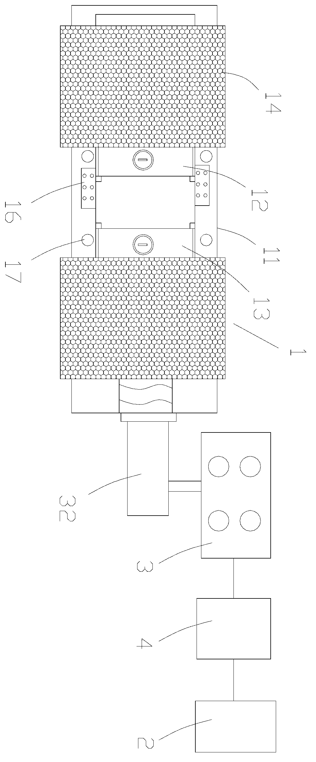
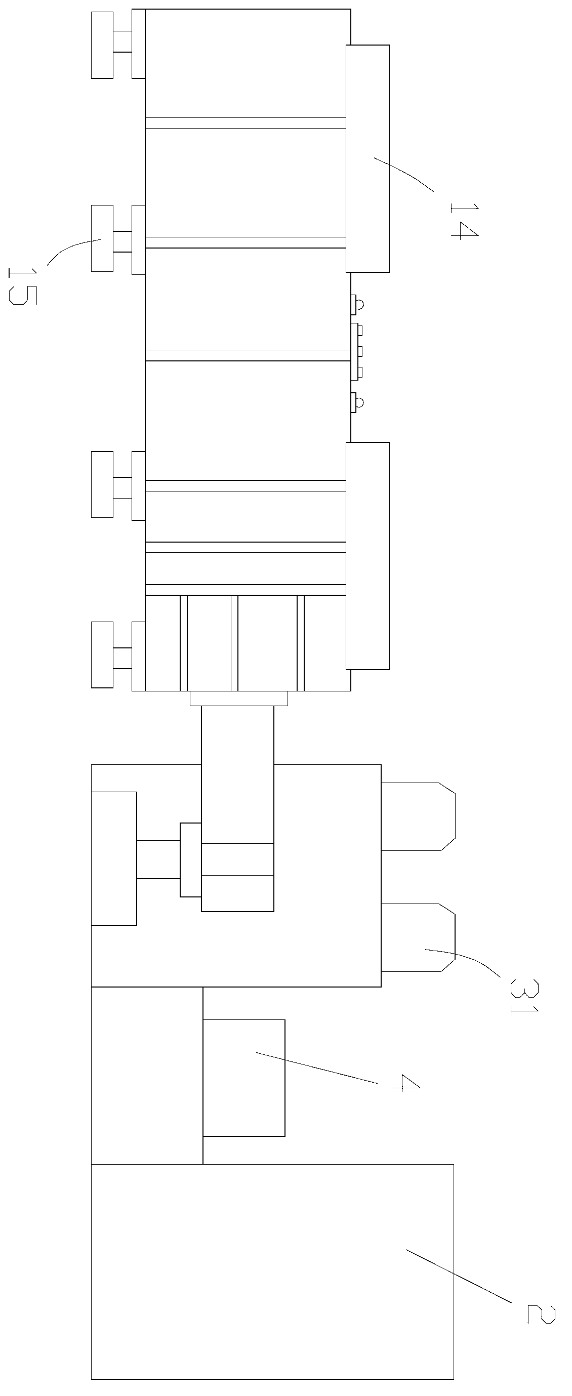
[0020] Such as figure 1 , figure 2 As shown, a traction belt tension test device includes a test mechanism 1, a power distribution cabinet mechanism 2, a tension mechanism 3 and a control mechanism 4. The tension mechanism 3 is connected to the test mechanism 1 for pulling the test mechanism 1 to move, and the power distribution cabinet The mechanism 2 is connected to the tension mechanism 3 and the testing mechanism 1 to provide power for the tension mechanism 3. The control mechanism 4 is connected to the power distribution cabinet mechanism 2 to control the operation of the entire device and to store and display the test results. The control mechanism 4 controls the power distribution cabinet mechanism 2 in a wired or wireless manner. The c...


PUM


Abstract

The invention provides a tension testing device of a traction belt, which relates to the technical field of tension testing equipment. The tension testing device comprises a testing mechanism, a power distribution cabinet mechanism, a tension mechanism and a control mechanism, wherein the tension mechanism is connected with the testing mechanism and used for pulling the testing mechanism to move; the power distribution cabinet mechanism is connected with the tension mechanism and the testing mechanism so as to provide a power supply to the tension mechanism; and the control mechanism is connected with the power distribution cabinet mechanism, is used for controlling the operation of the whole device and can be used for storing and displaying a testing result. The tension testing device of the traction belt, provided by the invention, has the advantages of simple structure, convenience for testing as well as safety and reliability in use, can be suitable for testing tensions of the traction belts or safety belts with various sizes, and can be used for displaying the testing results in real time.

Description

technical field [0001] The invention relates to the technical field of tension testing equipment, in particular to a device for tension testing of traction belts. Background technique [0002] Due to various safety regulations, workers working at high places, such as on the steel beams of vertical buildings, need to be restrained from falling. A common method for this purpose is to use a harness or harness which is worn by the worker and attached to a fixed hinge point. The hinge point can be any fixed component, such as an I-beam on a building. Thus, once the worker is linked, he can avoid falling to the ground when he falls from the structure. There are also ropes used for binding goods or traction belts used for traction, all of which must have good pulling force and be able to withstand a large pulling force to ensure the safety of people and goods. Therefore, all kinds of belts need to be tested for tension after they are manufactured to see if they meet the standard...

Claims


Application Information

Patent Timeline
Patent Type & Authority Applications(China)
IPC IPC(8): G01N3/08
Inventor 王克祥
Owner 安徽恒索带业有限公司
Why Eureka
Try Eureka