Laminated inductor
An inductor and multilayer technology, applied in the field of multilayer inductors, can solve problems such as low volume resistivity, and achieve the effects of increasing L value, increasing strength, and increasing strength
Active Publication Date: 2013-02-13
TAIYO YUDEN KK
View PDF5 Cites 11 Cited by
- Summary
- Abstract
- Description
- Claims
- Application Information
AI Technical Summary
Problems solved by technology
On the contrary, the volume resistivity of the material itself is much lower than that of conventional ferrite
Method used
View moreImage
Smart ImageViewing Examples
Examples
Embodiment
[0064] Hereinafter, the present invention will be described more specifically by way of examples. However, this invention is not limited to the aspect described in these Examples.
Login to View More PUM
 Abstract
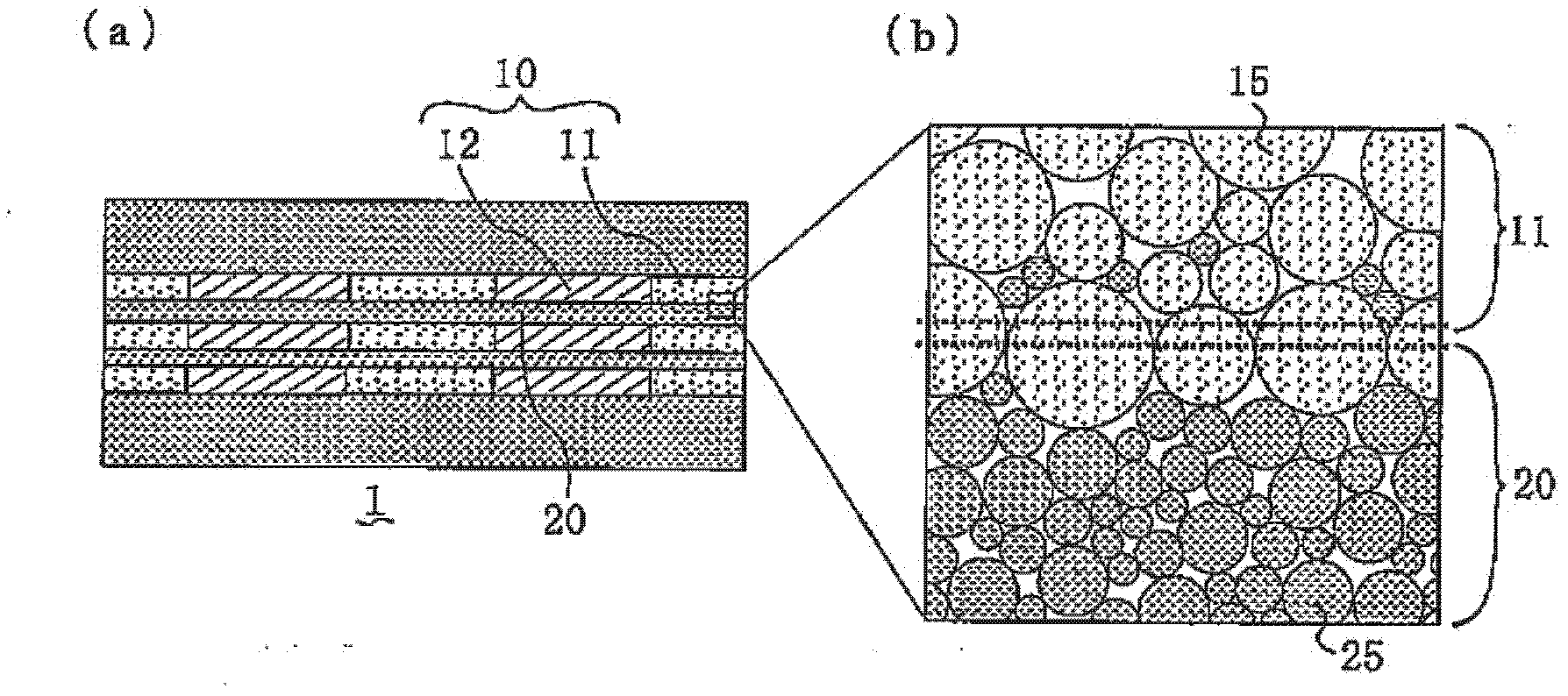
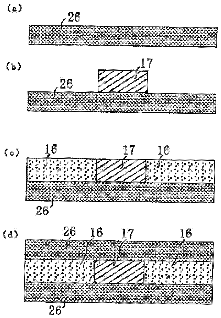
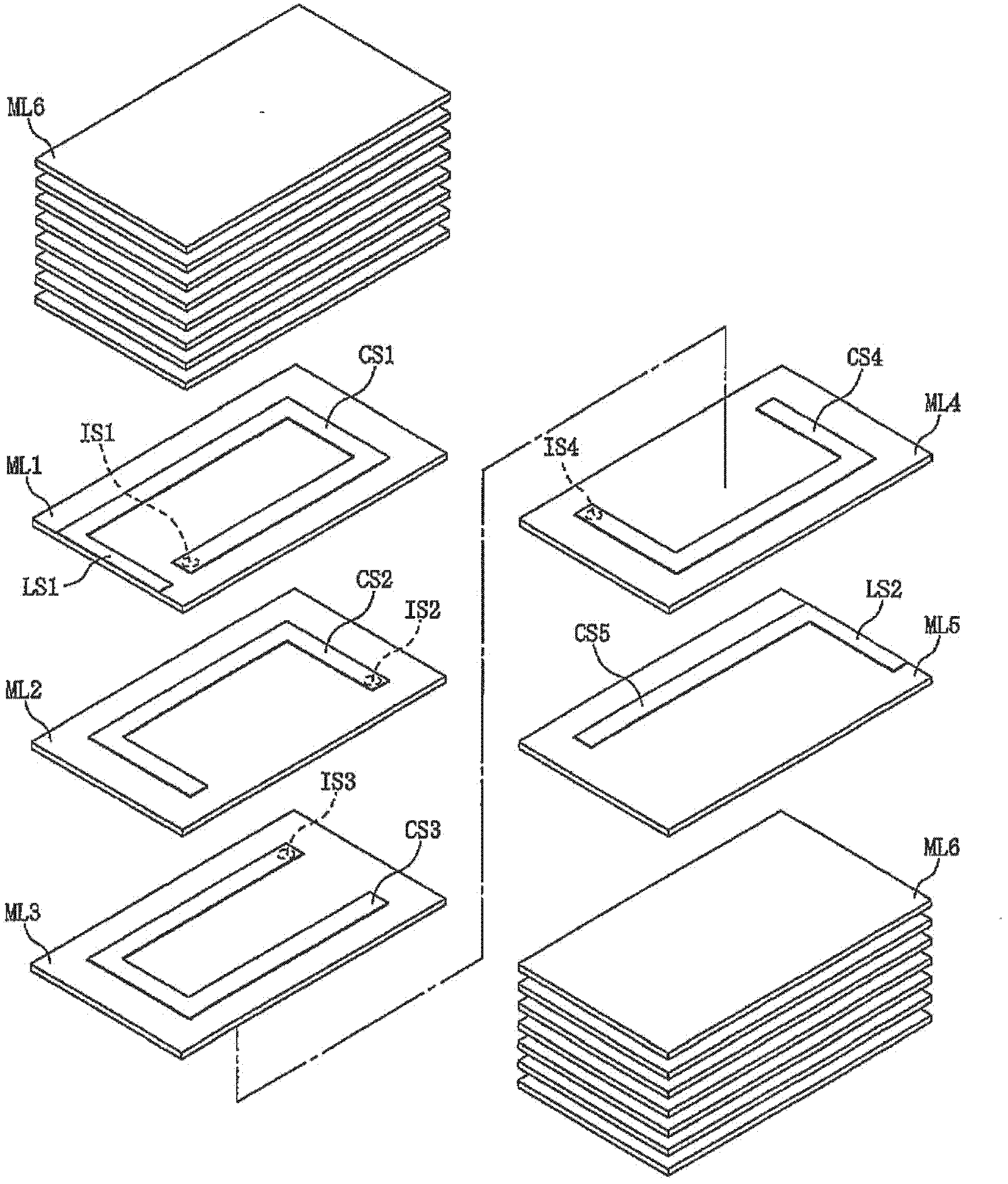
A laminated inductor having a laminate structure constituted by magnetic layers and internal conductive wire-forming layers, wherein the magnetic layer is formed by soft magnetic alloy grains, the internal conductive wire-forming layer has an internal conductive wire and a reverse pattern portion around it, and the reverse pattern portion is formed by soft magnetic alloy grains whose constituent elements are of the same types as those of, and whose average grain size is greater than that of, the soft magnetic alloy grains constituting the magnetic layer.
Description
technical field [0001] The present invention relates to a multilayer inductor. Background technique [0002] Conventionally, as one of the methods of manufacturing multilayer inductors, there is known a method of printing internal conductor patterns on ceramic green sheets containing ferrite and the like, and laminating and firing these sheets. [0003] According to Patent Document 1, there is disclosed a method of manufacturing a laminated chip inductor obtained by crimping and firing an unfired ceramic laminate on which a conductor pattern is formed. In the manufacturing method of Patent Document 1, an auxiliary magnetic material layer is provided on a magnetic material green sheet at least around a conductor pattern, and the thickness of the auxiliary magnetic material layer after firing is greater than that of the conductor pattern after firing. [0004] In recent years, multilayer inductors have been required to increase the current (that is, to increase the value of t...
Claims
Login to View More Application Information
Patent Timeline
 Patent Type & Authority Applications(China)
IPC IPC(8): H01F17/00H01F37/00
CPCH01F1/24H01F17/0013H01F27/255H01F27/28H01F1/33H01F2017/0066H01F17/00
Inventor 小林朋美松浦准新井隆幸八矢正大大竹健二
Owner TAIYO YUDEN KK
Features
- R&D
- Intellectual Property
- Life Sciences
- Materials
- Tech Scout
- Unparalleled Data Quality
- Higher Quality Content
- 60% Fewer Hallucinations
Learn More Browse by: Latest US Patents, China's latest patents, Technical Efficacy Thesaurus, Application Domain, Technology Topic, Popular Technical Reports.
© 2025 PatSnap. All rights reserved.Legal|Privacy policy|Modern Slavery Act Transparency Statement|Sitemap|About US| Contact US: help@patsnap.com


