Controllable electronic connector

A technology for controlling electronics and connectors, which is applied in the direction of connection and connection device components, circuits, etc., and can solve problems such as uncontrollable signal and working signal combination

Inactive Publication Date: 2013-02-13
JIH VEI ELECTRONICS KUSN
View PDF3 Cites 0 Cited by
  • Summary
  • Abstract
  • Description
  • Claims
  • Application Information

AI Technical Summary

Problems solved by technology

[0003] The current electronic connector has a simple structure and is connected with other electrical components. It can only accept one electrical signal, but cannot accept more than two electrical signals, and cannot combine control signals with working signals.

Method used


Image

  • Controllable electronic connector

Examples


Embodiment Construction

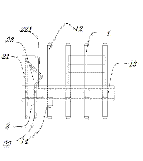
[0016] The present invention will be described in further detail below in conjunction with the accompanying drawings.

[0017] Such as figure 1 As shown, a controllable electronic connector of the present invention includes a plurality of first pin needles 12, the first pin needles 12 are connected to each other and fixed by plastic parts 13 to form a first pin needle group 1, and the first pin needles 12 have at least two ends It is exposed, and also includes a control pin needle group 2 connected to the first pin needle group 1, and the control pin needle group 2 is provided with several control pin needles. When in use, the first pin group 1 is connected to one electrical system, and the control pin group 2 is connected to another electrical system, so that two electrical signals can be received at the same time, only when both electrical systems send out electronic signals , the present invention controls the electronic connector to transmit the signal, thereby realizing ...


PUM


Abstract

The invention discloses a controllable electronic connector, comprising a plurality of first pins, wherein the first pins are mutually connected, and are fixedly arranged through a plastic piece, so as to form a first pin group; at least two heads of each first pin are exposed. The controllable electronic connector further comprises a control pin group connected on the first pin group; and a plurality of control pins are arranged on the control pin group. The first pin group is connected with an electric system, and the control pin group is connected with the other electric system so that two electric signals can be received simultaneously. When the two electric systems send the electronic signals, the controllable electronic connector provided by the invention controls an electronic connection piece to transmit the signals, so that the combination of the control signals and the working signals can be realized.

Description

technical field [0001] The invention relates to an electronic connector. Background technique [0002] Electronic connectors (also often referred to as circuit connectors, electrical connectors) bridge two conductors on a circuit so that current or signals can flow from one conductor to another conductor. It is widely used in various electrical circuits and plays the role of connecting or disconnecting current or signals. This connection may be temporary and easily plugged in at any time, or it may be a permanent junction between electrical equipment or wires. [0003] The current electronic connector has a simple structure and is connected with other electrical components. It can only accept one type of electrical signal, but cannot accept more than two types of electrical signals, and cannot combine control signals with working signals. Contents of the invention [0004] The technical problem to be solved by the present invention is to provide an electronic connect...

Claims


Application Information

Patent Timeline
Patent Type & Authority Applications(China)
IPC IPC(8): H01R13/02H01R13/40H01R13/46H01R13/66
Inventor 郭土水江清源
Owner JIH VEI ELECTRONICS KUSN
Why Eureka
Try Eureka