Protection circuit suitable for initiating explosive device on two-stage ignition bomb

A technology for protecting circuits and pyrotechnics, applied in the field of safety protection of pyrotechnics, can solve the problems of false ignition of pyrotechnics, poor direct protection, etc., achieve reliable ignition, ensure safety protection, reliability and safety high effect

Active Publication Date: 2013-02-13
BEIJING INST OF ELECTRONICS SYST ENG
View PDF5 Cites 16 Cited by
  • Summary
  • Abstract
  • Description
  • Claims
  • Application Information

AI Technical Summary

Problems solved by technology

[0003] The present invention aims to solve the problem that the existing safety protection method of explosives will lead to incorrect ignition of pyrotechnics and poor direct protection, and provides a protection circuit suitable for two-stage ignition bombs.

Method used


Image

  • Protection circuit suitable for initiating explosive device on two-stage ignition bomb
  • Protection circuit suitable for initiating explosive device on two-stage ignition bomb
  • Protection circuit suitable for initiating explosive device on two-stage ignition bomb

Examples


specific Embodiment approach 1

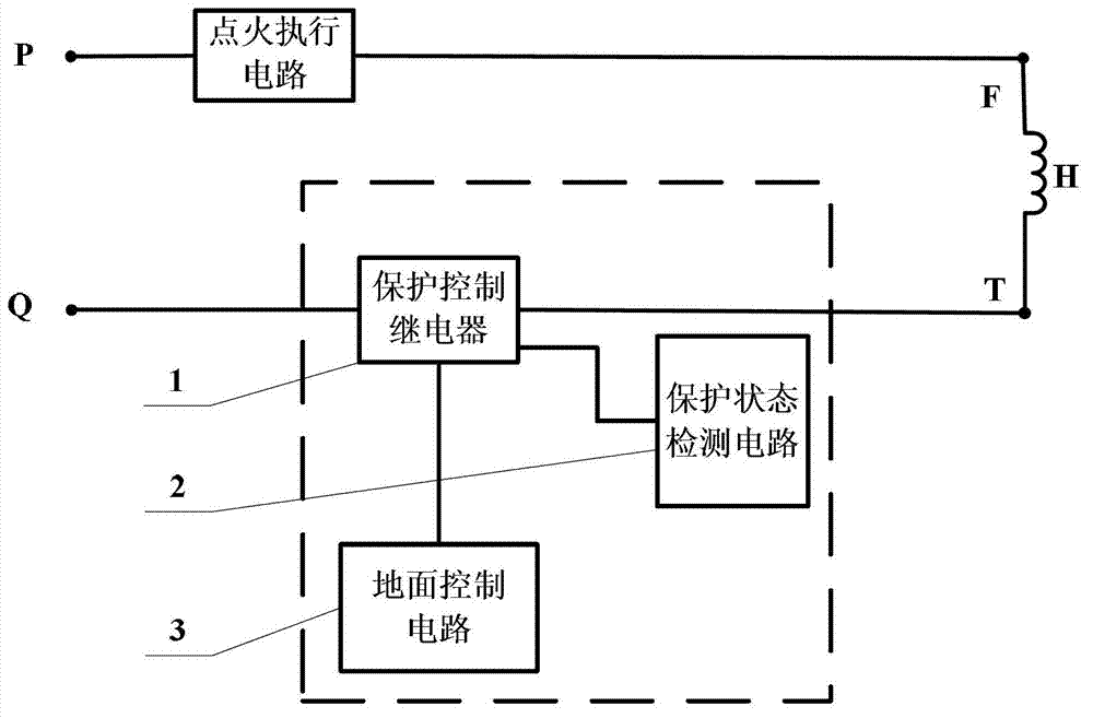
[0018] Specific implementation mode one: the following combination Figure 1 to Figure 2 Describe this embodiment, the protection circuit applicable to the pyrotechnics on the two-stage ignition bomb described in this embodiment, it includes a protection control relay 1, a protection state detection circuit 2 and a ground control circuit 3,

[0019] One end of the protection control relay 1 is connected to the negative power supply terminal Q of the ignition power supply, the other end of the protection control relay 1 is connected to the negative terminal T of pyrotechnic activation, and the control signal input terminal of the protection control relay 1 is connected to the control signal output terminal of the ground control circuit 3 , the control signal output end of the protection control relay 1 is connected to the control signal input end of the protection state detection circuit 2 .

specific Embodiment approach 2

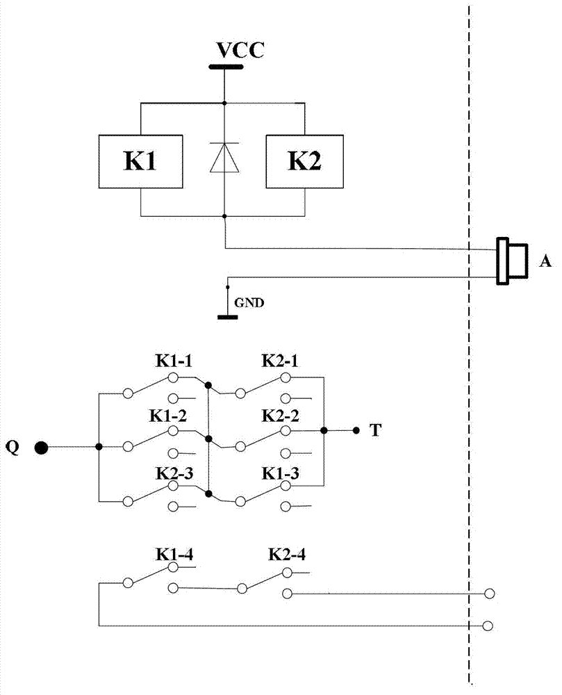
[0020] Specific implementation mode two: the following combination Figure 1 to Figure 2 Describe this embodiment, this embodiment is a further description of Embodiment 1, the protection circuit is composed of a first electromagnetic relay K1, a second electromagnetic relay K2 and a diode D,

[0021] The moving contact of the first group of contacts K1-1 of the first electromagnetic relay K1 is connected to the power supply negative terminal Q of the ignition power supply, and the normally closed static contact of the first group of contacts K1-1 is connected to the second electromagnetic relay K2. The moving contact of a group of contacts K2-1, the normally closed static contact of the first group of contacts K2-1 is connected to the active negative terminal T of the pyrotechnic device;

[0022] The moving contact of the second group of contacts K1-2 of the first electromagnetic relay K1 is connected to the power supply negative terminal Q of the ignition power supply, and t...


PUM


Abstract

The invention discloses a protection circuit suitable for an initiating explosive device on a two-stage ignition bomb. The protection circuit belongs to the technical field of safety protection of the initiating explosive device on the bomb, and solves problems of delayed explosion and poor direct protectiveness of the initiating explosive device caused by a safety protection mode of the conventional initiating explosive device on the bomb. The protection circuit comprises a protection control relay, a protection state detection circuit and a ground control circuit; one end of the protection control relay is connected with a negative power supply end Q of an ignition power supply; the other end of the protection control relay is connected with a negative activating end T of the initiating explosive device; a control signal input end of the protection control relay is connected with a control signal output end of the ground control circuit, and the control signal output end of the protection control relay is connected with the control signal input end of the protection state detection circuit. The protection circuit is suitable for safety protection of the initiating explosive device on the two-stage ignition bomb.

Description

technical field [0001] The invention relates to a protection circuit applicable to explosive devices on two-stage ignition bombs, and belongs to the technical field of safety protection of explosive devices on bombs. Background technique [0002] Whether the pyrotechnic product is fired normally is related to the success or failure of the test, and whether the safety protection measures for the pyrotechnic device are effective also relates to whether the test can be carried out normally. See image 3 shown. from image 3 It can be seen from the figure that the traditional protection method of pyrotechnics is to directly lead the active positive and negative terminals of pyrotechnics to the ground for short-circuit protection. The disadvantage of this protection method is that the protection line is long. Improper, there may be interference voltage, which may lead to wrong ignition of pyrotechnic devices, and poor direct protection; on the other hand, it cannot meet the timi...

Claims


Application Information

Patent Timeline
Patent Type & Authority Applications(China)
IPC IPC(8): H02H3/08
Inventor 董淑英薛健程鹏李存洲
Owner BEIJING INST OF ELECTRONICS SYST ENG
Why Eureka
Try Eureka