
Air conditioner refrigerating capacity and heating capacity testing method and air pipe box heat meter

The technology of an air conditioner and a calorimeter is applied in the field of the cooling capacity and heating capacity test of the air conditioner and the air duct box calorimeter, and can solve the problem of high manufacturing cost of the cooling capacity and heating capacity of the air conditioner.

Inactive Publication Date: 2013-02-20
ZHEJIANG ACAD OF SCI & TECH FOR INSPECTION & QUARANTINE
View PDF6 Cites 10 Cited by
  • Summary
  • Abstract
  • Description
  • Claims
  • Application Information

AI Technical Summary

Problems solved by technology

[0011] The invention provides a method for measuring the cooling capacity and heating capacity of an air conditioner that can independently measure the cooling capacity and heating capacity of the air conditioner and can also be used as an auxiliary measurement method for the indoor enthalpy difference method, and the required equipment manufacturing cost is relatively low, and realizes the method. The air duct box calorimeter of the method solves the problem that the existing air conditioner cooling capacity and heating capacity measurement method cannot not only independently measure the cooling capacity and heating capacity of the air conditioner, but also be used as an auxiliary measurement method for the indoor enthalpy difference method. The problem of high production cost of the required equipment

Method used


Image

  • Air conditioner refrigerating capacity and heating capacity testing method and air pipe box heat meter
  • Air conditioner refrigerating capacity and heating capacity testing method and air pipe box heat meter

Examples


Embodiment Construction

[0069] The present invention will be further described below in conjunction with the accompanying drawings and embodiments.

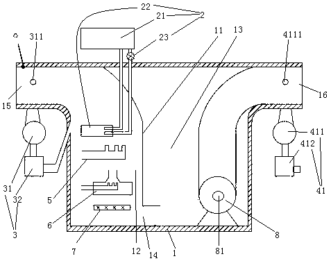
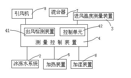
[0070] see figure 1 , an air duct box calorimeter, including an air duct box 1, a chilled water system 2, an inlet air temperature measuring device 3 and an air outlet detection device 41. The air duct box 1 is provided with an insulating layer. The air duct box 1 is divided into a first chamber body 12 and a second chamber body 13 by a partition 11 . The partition 11 is provided with a via hole 14 . The first chamber body 12 is provided with an air duct box air inlet 15 . The first chamber body 12 is provided with a heating device 5 , a humidifying device 6 and a mixer 7 . The second chamber body 13 is provided with an air duct box air outlet 16 . An induced draft fan 8 is arranged in the second chamber body 13 . The air inlet 81 of the induced draft fan is located in the second chamber body 13 . The air outlet of induced draft fan 8 is communic...


PUM


Abstract

The invention relates to an air conditioner refrigerating capacity and heating capacity testing method and an air pipe box heat meter applicable to the method. The air pipe box heat meter comprises an air pipe box, a freezing water system and a measurement control device, wherein the freezing water system comprises a freezing water coiled pipe arranged in the air pipe box; and the air pipe box is internally provided with a heating device, a humidifying device and a draught fan. The measurement method comprises the following steps that after an air conditioner starts and is led into an air pipe box; and the measurement control device controls work states of the freezing water system, the heating device, the humidifying device and the draught fan so that a dry ball temperature and a wet ball temperature of air which flows out of the air pipe box are the same as a dry ball temperature and a wet ball temperature of air which flows into an air inlet of the air conditioner to be measured; and therefore, the refrigerating capacity and the heating capacity of the air conditioner to be measured are calculated. According to the air conditioner refrigerating capacity and heating capacity testing method and the air pipe box heat meter applicable to the method, the problems that the existing method can not independently measure the refrigerating capacity and the heating capacity of the air conditioner and can not be used as an auxiliary testing method of an enthalpy potential method, and the manufacturing cost of needed equipment is high are solved.

Description

technical field [0001] The invention relates to a method for testing the cooling capacity and heating capacity of an air conditioner and an air duct box calorimeter suitable for the method. Background technique [0002] In my country's national standard GB / T7725-2004 "Room Air Conditioners", it is recommended to use the room calorimeter method and the enthalpy difference method to test the cooling and heating capacity of air conditioners; in the international standard ISO5151-2010 "Non-ducted air conditions and heat pumps-Testing and rating for performance" (Chinese is the performance test and rating of air conditioners without ducts and heat pumps), it is proposed to use the room calorimeter method and the enthalpy difference method to test the cooling capacity and heating capacity of the air conditioner. It is also recommended that when using the indoor enthalpy difference method for measurement, the following methods can be selected as auxiliary measurement methods: ...

Claims


Application Information

Patent Timeline
Patent Type & Authority Applications(China)
IPC IPC(8): G01K17/08
Inventor 马南
Owner ZHEJIANG ACAD OF SCI & TECH FOR INSPECTION & QUARANTINE
Learn More