
Fuse unit, mold structure, and molding method using mold structure

A fuse and mold technology, applied in applications, household components, electrical components, etc., can solve problems such as defects and deformation, and achieve the effect of increasing supporting force

Inactive Publication Date: 2013-02-20
YAZAKI CORP
View PDF7 Cites 2 Cited by
  • Summary
  • Abstract
  • Description
  • Claims
  • Application Information

AI Technical Summary

Problems solved by technology

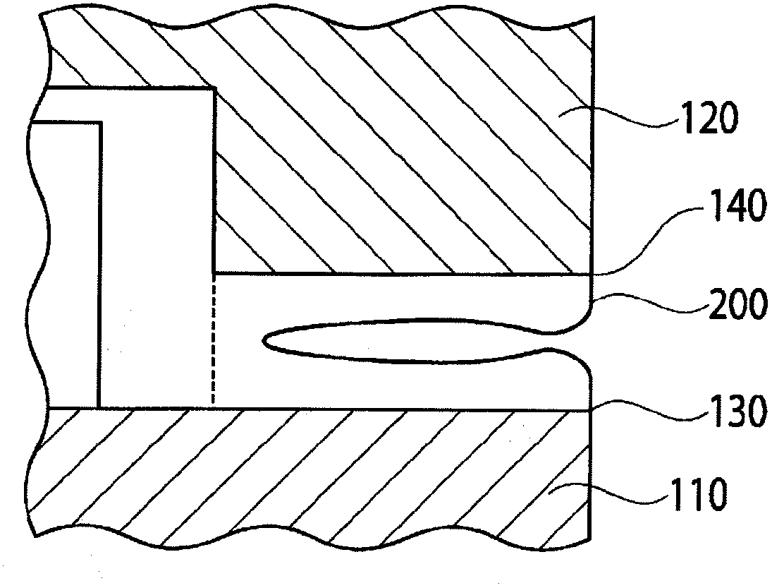
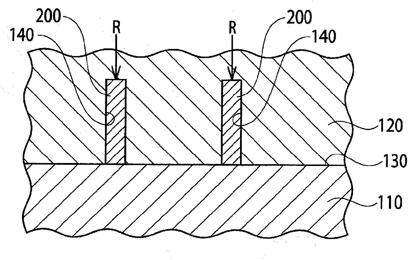
The tuning fork terminal 200 may be deformed due to the above reasons resulting in defective goods

Method used


Image

  • Fuse unit, mold structure, and molding method using mold structure
  • Fuse unit, mold structure, and molding method using mold structure
  • Fuse unit, mold structure, and molding method using mold structure

Examples


Embodiment Construction

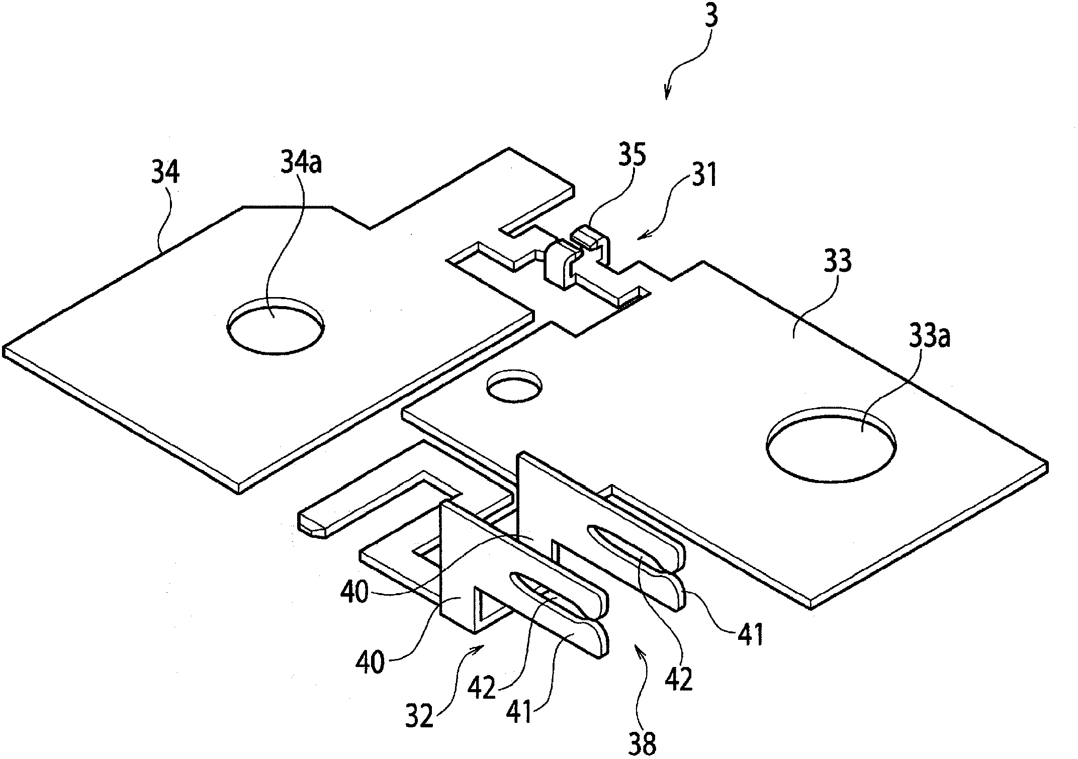
[0035] Embodiments of the present invention will be described in detail below with reference to the accompanying drawings. Figures 3 to 13 is an embodiment of the present invention. image 3 and 4 The busbar is shown. Figure 5 is a perspective view showing the main part of the mold structure. Figure 6 is a sectional view showing the main part of the mold structure. Figure 7 is a perspective view of the busbar. Figure 8 and 9 is a perspective view of a supported state of the tuning fork terminal at the time of molding. Figure 10 and 11 The electrical components being molded are shown. Figure 12 and 13 A perspective view of post-processing of the molded electrical component is shown.

[0036] Such as image 3 and 4 As shown, the busbar 3 applied to the mold structure 1 of this embodiment is formed by arranging the tuning fork terminals 32 on the main circuit unit 31 . At the main body circuit unit 31 , a power side terminal plate 33 having formed power side stud...


PUM


Abstract

A mold structure (1) includes a fixed mold (4) and a movable mold (5) for burying, integrally with molding of a plastic molded article (26), a bus bar (3) in which a tuning-fork terminal (32) is provided on a main body circuit unit (31). When the fixed mold (4) and the movable mold (5) are joined together, the terminal base (40) of the tuning-fork terminal (32) is held between a terminal base receiving portion (13) of the fixed mold (4) and a terminal base abutting portion (17) of the movable mold (5) while the tuning-fork terminal (32) is projected outside a cavity which is formed in such a way that the mold main body portions of the fixed mold (4) and the movable mold (5) are joined each other and into the inside of which a resin is injected.

Description

technical field [0001] The present invention relates to a mold structure for manufacturing electrical parts such as a fuse unit by insert molding a bus bar, a molding method using the mold structure, and a fuse unit. Background technique [0002] As described in Patent Document 1, for example, a fusible unit is connected to an on-vehicle battery and wires to supply power to an on-vehicle load, and the fusible unit is installed at a position for receiving the influence of vehicle body vibration. In the position affected by the vibration of the vehicle body, the manufacture is performed by injecting resin in a state where the bus bar with the formed main body circuit unit is inserted into the molding mold in consideration of damage to the unit main body and the bus bar due to resonance. Since the bus bar and the resin molded product are integrated by insert molding the bus bar as described above, resonance due to vibration can be suppressed. [0003] On the other hand, there ...

Claims


Application Information

Patent Timeline
Patent Type & Authority Applications(China)
IPC IPC(8): H01H85/045H01H69/02H01H85/175
CPCH01R13/112H01H69/02H01H85/0456H01H2085/025H01H85/10H01H85/045H01H85/175B29C45/04B29C45/045B29C45/14B29C45/14008B29C45/14065B29C45/14467B29C2045/1486B29L2031/3493B29L2031/36H01H85/04H01R25/14H01R43/16H01R43/24
Inventor 小野田伸也
Owner YAZAKI CORP
Learn More