Metal chip safe cleaning device

A technology for cleaning devices and metal fragments, applied in the field of tools, can solve problems such as easy cuts to workers, and achieve the effect of ensuring that they are not scratched

Inactive Publication Date: 2013-02-27
SHENYANG XINDA INFORMATION SCI & TECH
View PDF0 Cites 6 Cited by
  • Summary
  • Abstract
  • Description
  • Claims
  • Application Information

AI Technical Summary

Problems solved by technology

[0002] At present, some industrial and mining enterprises need to clean up metal fragments during operation. When there are few metal fragments and a large area, most of them use manual cleaning. The edges of metal fragments are relatively sharp, which is easy to cut the staff.

Method used


Image

  • Metal chip safe cleaning device

Examples


Embodiment Construction

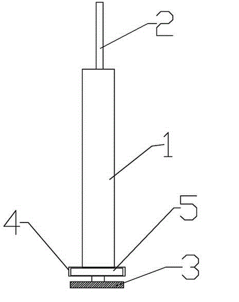
[0009] Such as figure 1 As shown, the metal fragment safety cleaning device includes a housing 1, a connecting rod 2, an annular groove 4, a magnetic ring 5, and a baffle 3. The annular groove 4 is fixed at one end of the housing 1, and the connecting rod 2 It is arranged in the housing 1 and is coaxially connected with the housing 1. The length of the connecting rod 2 is greater than the length of the housing 1, and a baffle 3 is fixed at one end of the connecting rod 2; the magnetic ring 5 is arranged in the annular groove 4 .

[0010] When working, lift the connecting rod 2 upwards to make the baffle 3 close to the annular groove 4 so that the metal fragments can be attracted to the surface of the baffle 3, and push the connecting rod 2 downwards to keep the metal fragments away from what the magnetic ring 5 can attract. Range, metal fragments can be moved to the recycling place.


PUM


Abstract

The invention belongs to the technical field of tools, in particular to a metal chip safe cleaning device, and aims at providing the metal chip safe cleaning device which protects workers from being scratched and is simple to operate. By means of the technical scheme, the metal chip safe cleaning device comprises a shell body, a connecting rod, an annular groove, a magnet ring and a blocking plate. The annular groove is fixed at one end of the shell body, the connecting rod is arranged in the shell body and in coaxial connection with the shell body, the length of the connecting rod is larger than that of the shell body, one end of the connecting rod is fixed on the blocking plate, and the magnet ring is arranged in the annular groove.

Description

Technical field [0001] The invention belongs to the technical field of tools, and particularly relates to a safety cleaning device for metal fragments. Background technique [0002] At present, some industrial and mining enterprises encounter situations where metal fragments need to be cleaned up during operations. When metal fragments are less spread over a large area, they mostly use manual cleaning. The edges of the metal fragments are relatively sharp and easy to cut workers. Summary of the invention [0003] In order to overcome the defects of the prior art, the purpose of the present invention is to provide a metal fragment safety cleaning device that protects workers from being scratched and is simple to operate. [0004] The technical solution adopted by the present invention includes a housing, a connecting rod, an annular groove, a magnetic ring, and a baffle. The annular groove is fixed at one end of the housing, and the connecting rod is arranged in the housing and is th...

Claims


Application Information

Patent Timeline
Patent Type & Authority Applications(China)
IPC IPC(8): B03C1/02
Inventor 王春艳颉垚
Owner SHENYANG XINDA INFORMATION SCI & TECH
Why Eureka
Try Eureka