Bus bar punching machine

A punching machine and busbar technology, applied in the direction of punching tools, metal processing equipment, manufacturing tools, etc., can solve the problems of a large number of molds, inconvenient portability, low efficiency, etc., and achieve small molds, simple and light structure, and easy handling. Effect

Inactive Publication Date: 2013-02-27
陈伟民
View PDF4 Cites 5 Cited by
  • Summary
  • Abstract
  • Description
  • Claims
  • Application Information

AI Technical Summary

Problems solved by technology

[0002] The currently used busbar punching machine has the following disadvantages: the punching mold is a pair of molds of one specification, the number of molds is large, the size is large, and it is inconvenient to carry. When punching the busbar, the X-direction displacement is positioned by a stop , slow operation, low efficiency

Method used


Image

  • Bus bar punching machine
  • Bus bar punching machine
  • Bus bar punching machine

Examples


Embodiment Construction

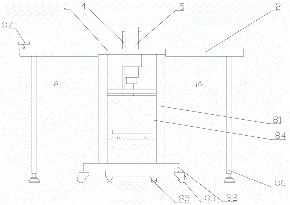
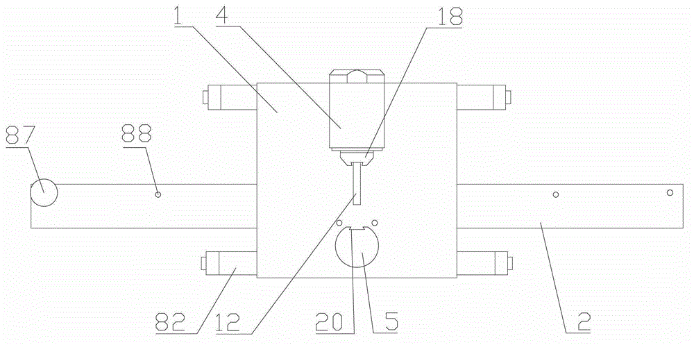
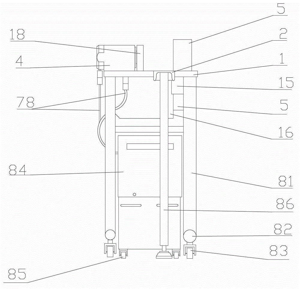
[0034] Such as Figure 1~14 Shown: It includes a platen 1, a supporting plate 2, a cylinder 4 connected with a power unit, a pressure head 18, a column 5, and a punching die. The platen is used to load or connect related parts. The cylinder socket 11, the guide groove 12, and the column fixing hole 13 are arranged. The cylinder is inserted into the cylinder socket through the cylinder foot 14 provided on the lower wall of the cylinder. The cylinder is fixed to the table by bolts, and the column passes through the column. The fixing hole 13 is also sleeved on the reinforcing sleeve 15 provided under the fixing hole of the column; the reinforcing sleeve has the effect of strengthening the fixing of the column, and the lower wall of the table is connected with a reinforcing plate perpendicular to the table from the rear end of the cylinder to the direction of the column 16. The reinforcing plate is connected with the column and the reinforcing sleeve; the reinforcing plate plays th...


PUM


Abstract

The invention relates to a bus bar punching machine, comprising a table plate, support plates, an oil cylinder, a press head, a vertical column and a punching die, wherein an oil cylinder insertion hole, a guide groove and a vertical column fixing hole which are longitudinally arrayed are sequentially formed on the table plate; the oil cylinder and the vertical column are fixed on the table plate; a reinforcing plate is arranged on the lower wall surface of the table plate; a material-falling inclined groove which is formed towards a side surface is formed on the upper surface of the reinforcing plate; a section of guide groove is correspondingly formed above the material-falling inclined groove, and is through from top to bottom; the press head is arranged at the front end of the piston rod of the oil cylinder and towards the direction of the vertical column; a first dovetail groove is formed at one side facing the vertical column, of the press head, and a second dovetail groove is formed at one side facing the press head, of the vertical column; the support plates are located at the both sides of the table plate; a slide foot is arranged below the press head and arranged in the guide groove, and can be used for guiding the press head to slide back and forth along the direction of the guide groove; and the punching die is arranged on the press head of the oil cylinder and the vertical column. The bus bar punching machine disclosed by the invention has the advantages of being simple, light and small in structure, small in die, light in machine body, firm in table plate and easy to carry.

Description

Technical field [0001] The invention relates to the field of bus bar processing equipment, in particular to a bus bar punching machine with light structure and diverse functions. Background technique [0002] The busbar punching machines currently in use have the following shortcomings: the punching die is one type of die, the number of dies is large, the size is large, and it is not convenient to carry. When the bus is punched, the X-direction displacement is positioned by the stop when the bus is punched. , The operation is slow and the efficiency is low. Summary of the invention [0003] The purpose of the present invention is to provide a busbar punching machine with a light structure. [0004] The purpose of the present invention is achieved as follows: it includes a table, a support plate, an oil cylinder connected with a power device, a pressure head, a column, and a punching die. The table is sequentially provided with longitudinally arranged oil cylinder insertion holes, g...

Claims


Application Information

Patent Timeline
Patent Type & Authority Applications(China)
IPC IPC(8): B21D28/24B21D28/34
Inventor 陈伟民
Owner 陈伟民
Why Eureka
Try Eureka