Image forming apparatus including a collecting portion inside guide members to collect and store liquid droplets

a technology of image forming apparatus and guide member, which is applied in the direction of electrographic process apparatus, instruments, optics, etc., can solve the problems of affecting the transfer part, and affecting the overall size of the apparatus

Active Publication Date: 2012-04-24
RICOH KK
View PDF19 Cites 6 Cited by
  • Summary
  • Abstract
  • Description
  • Claims
  • Application Information

AI Technical Summary

Benefits of technology

[0016]Example aspects of the present patent application provide an image forming apparatus that has a compact body and a less expensive configuration and can eliminate water droplets without providing any additional unit and prevent a production of defective images due to water droplets from condensation of vapor even immediately after printing a large amount of single-side copies.

Problems solved by technology

However, these approaches require additional components and add to the overall size of the apparatus, which is undesirable in the face of continued market demand for compact and inexpensive configurations.
This action can cause transfer failure at a transfer part such as a secondary transfer roller while forming an image, and produce defective images as a result.
Similarly, a duct member or other element or component to reduce or eliminate water droplets or condensation cannot be provided to prevent adhesion of water droplets to the transfer sheet guide plates because space for such an additional component is limited and cost can increase due to an increasing number of mechanical parts.
The accumulated water droplets can adhere to the transfer sheet to cause transfer failure at the transfer section when printing both sides of a next transfer sheet, which can produce defective images.

Method used


Image

  • Image forming apparatus including a collecting portion inside guide members to collect and store liquid droplets
  • Image forming apparatus including a collecting portion inside guide members to collect and store liquid droplets
  • Image forming apparatus including a collecting portion inside guide members to collect and store liquid droplets

Examples


exemplary embodiment 1

[0057]Referring to FIGS. 1 through 3, descriptions are given of a schematic configuration and operations of an image forming apparatus 100 according to Example Embodiment 1 of the present patent application.

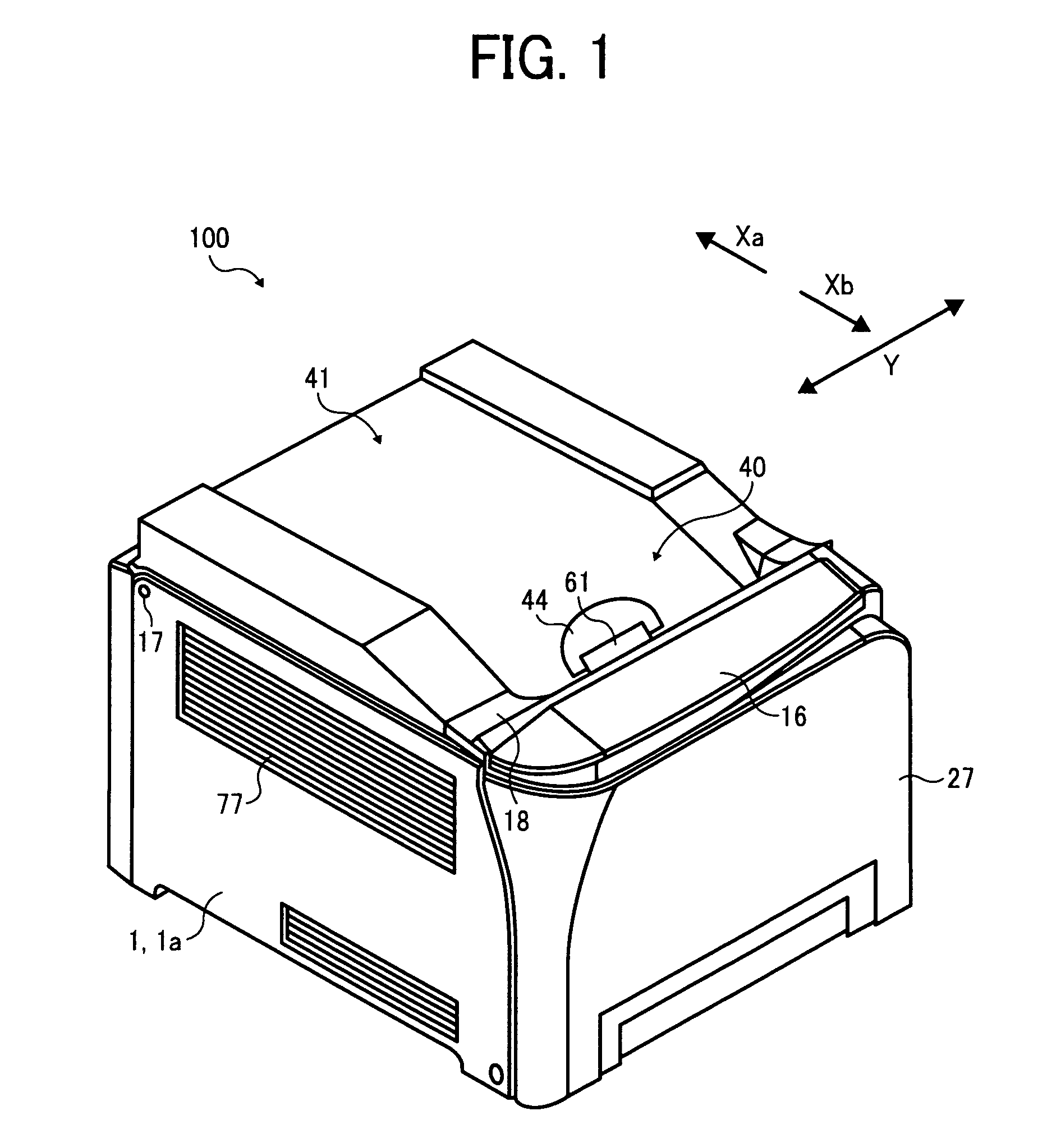
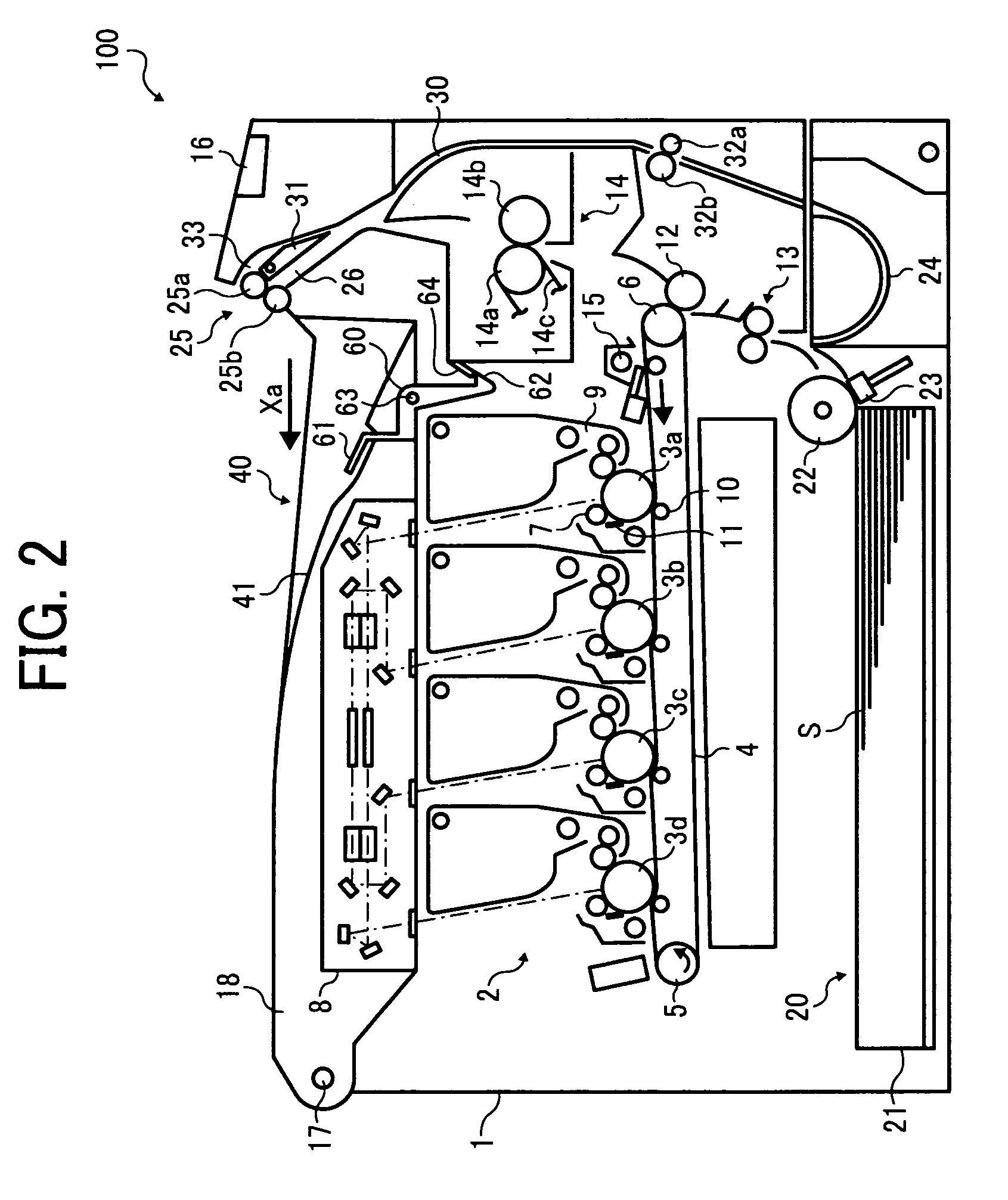
[0058]FIG. 1 illustrates a perspective view of the image forming apparatus 100, and FIG. 2 illustrates a vertical cross-section of an interior of the image forming apparatus 100 of FIG. 1.

[0059]The image forming apparatus 100 can be any of a copier, a printer, a facsimile machine, a plotter, and a multifunction printer including at least one of copying, printing, scanning, plotter, and facsimile functions. In this non-limiting exemplary embodiment, the image forming apparatus 100 functions as a full-color printing machine for electrophotographically forming a toner image based on image data on a recording medium (e.g., a transfer sheet).

[0060]The toner image is formed with four single toner colors, which are yellow, cyan, magenta, and black. Reference symbols “Y”, “C”, “M”, and “...

example embodiment 1

[0134]Referring to FIG. 7A, a description is given of the image forming apparatus 100 according to Example Embodiment 1 of the present patent application.

[0135]In FIG. 7A illustrating the configuration according to Example Embodiment 1, the image forming apparatus 100 includes hollow portions 67 and 69.

[0136]The hollow portion 67 is located above the fixing unit 14, between the fixing unit 14 and the sheet reverse path 30. The hollow portion 67 is surrounded by the upper fixing guide plate 70 and the outlet fixing guide plate 71. Both of the upper fixing guide plate 70 and the outlet fixing guide plate 71 serve as multiple guide members.

[0137]The hollow portion 69 is surrounded by the lower fixing guide plate 75. The lower fixing guide plate 75 is also included in the multiple guide members.

[0138]An air current that may include vapor is generated in a heated area of the fixing unit 14 during image forming and flows to the hollow portions 67 and 69 or to inner walls of the upper fixi...

example embodiment 2

[0141]Referring to FIG. 8, a description is given of the image forming apparatus 100 according to Example Embodiment 2 of the present patent application.

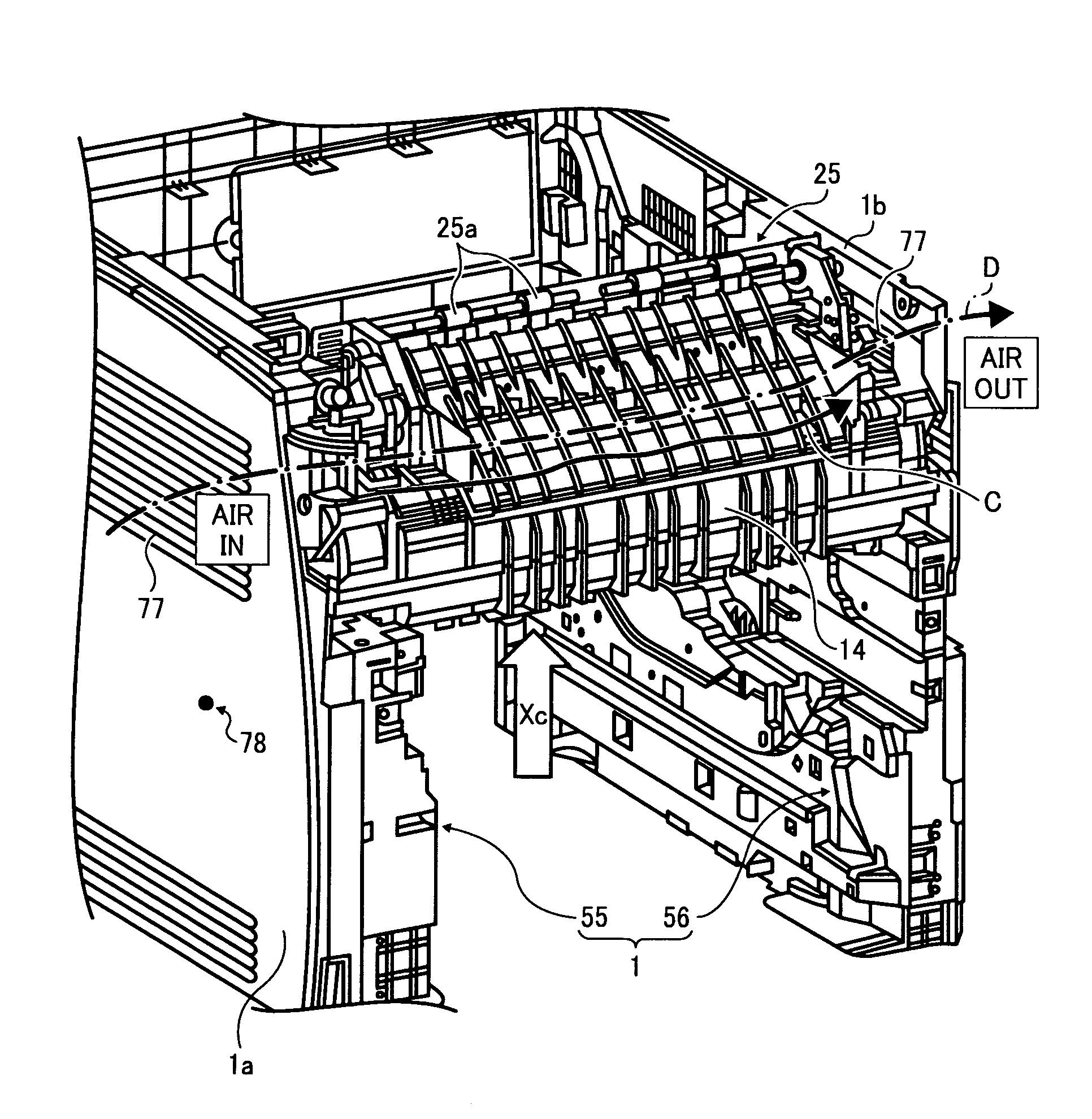
[0142]As shown in FIG. 8, the hollow portion 67 extends to enable an air current indicated by arrow B to flows in the hollow portion 67 in a direction substantially perpendicular to the direction Xc that is a direction of conveyance of the transfer sheet S. That is, the air current B travels in the hollow portion 67.

[0143]As previously shown in FIG. 4, the louver 77 is formed on each of the left external cover 1a of the left frame 55 and the right external cover 1b of the right frame 56. Since the temperature in the vicinity of the right side and the temperature in the vicinity of the left side in the main body 1 of the image forming apparatus 100 can be different due to design for air current control in the main body 1. For example, the temperature in the left side of the main body 1 of the image forming apparatus 100 is set to be ...


PUM


Abstract

An image forming apparatus includes a transfer unit, a fixing unit, a discharging unit, and multiple guide members. The transfer unit transfers an image onto a transfer sheet. The fixing unit fixes the image to the transfer sheet by application of heat and conveys the fixed transfer sheet to a further downstream portion of the image forming apparatus. The discharging unit discharges the transfer sheet to an external portion of the image forming apparatus. The multiple guide members form a sheet conveyance path that has first and second paths including a hollow portion defined by the multiple guide members to enable an air current generated during image forming to pass therethrough.

Description

CROSS-REFERENCE TO RELATED APPLICATIONS[0001]The present invention claims priority pursuant to 35 U.S.C. §119 from Japanese Patent Application No. 2008-173431, filed on Jul. 2, 2008 in the Japan Patent Office, the contents and disclosure of which are hereby incorporated by reference herein in their entirety.BACKGROUND OF THE INVENTION[0002]1. Field of the Invention[0003]Example embodiments of the present patent application relate to an image forming apparatus such as a copier, facsimile machine, printer, plotter, and multiple function machine including two or more functions of these apparatuses and devices that form images on both sides of a recording medium.[0004]2. Discussion of the Related Art[0005]Electrophotographic image forming apparatuses generally include a fixing unit that employs a heat fixing system for fixing a toner image formed on a recording medium to the recording medium by application of heat and pressure. During a fixing process performed by the heat fixing system...

Claims


Application Information

Patent Timeline
Patent Type & Authority Patents(United States)
IPC IPC(8): G03G21/20G03G15/00
CPCG03G15/6579G03G2215/00586
Inventor YAMAZOE, YOSHIKAZU
Owner RICOH KK
Why Eureka
Try Eureka