
Control device and method for chain board conveying device

A conveying device and control device technology, which is applied in the direction of conveyor control devices, conveyor objects, transportation and packaging, etc., can solve problems affecting the production and operation of polyester plants, increasing maintenance workload, and breaking chains and chain plates. Achieve the effect of reducing the maintenance workload of equipment, avoiding the chain from being pulled, and preventing the chain from being damaged

Inactive Publication Date: 2013-02-27
JIANGSU SHENJIU CHEM FIBER CO LTD
View PDF7 Cites 2 Cited by
  • Summary
  • Abstract
  • Description
  • Claims
  • Application Information

AI Technical Summary

Problems solved by technology

In actual operation, there is often no alarm after the derailment of the sprocket and the damage of the chain and disc, which greatly increases the maintenance workload and even affects the production and operation of the polyester plant in serious cases.
[0003] Disassemble the chain derailment protection switch for inspection, and found that the switch is a mechanical rotary cam switch, which rotates with the sprocket. In actual operation, PTA dust enters the inside of the cam switch along the shaft during the rotation of the sprocket, causing the switch to be damaged and invalid. When the chain is derailed The protection signal does not work, and the motor continues to run, causing the chain and chain plate to be damaged
In addition, the sprocket is driven by a variable frequency motor. When the sprocket derailment protection switch is triggered normally, the frequency converter has a certain deceleration ramp down time due to its own characteristics, and the motor still needs to run for a period of time before it can stop, which will also cause chain and chain plate pull bad

Method used


Image

  • Control device and method for chain board conveying device
  • Control device and method for chain board conveying device
  • Control device and method for chain board conveying device

Examples


Embodiment Construction

[0019] In order to make the object, technical solution and advantages of the present invention clearer, the present invention will be further described in detail below in conjunction with the accompanying drawings and embodiments. It should be understood that the embodiments described here are only used to explain the present invention, not to limit the present invention.

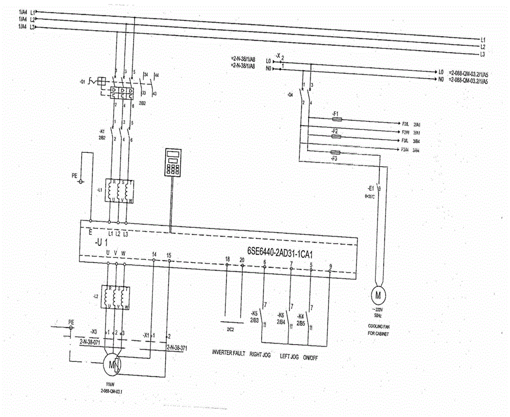
[0020] The present invention proposes a control device for a chain plate conveying device, which includes a three-stage conveying chain plate, a vibrating device and a control system. figure 1 Shows the power wiring diagram of the first stage chain drive motor.

[0021] Preferably, the device includes a non-contact position detection device, and the non-contact position detection device includes a proximity switch and a positioning piece fixed on the rotating shaft of the chain plate derailment detection device.

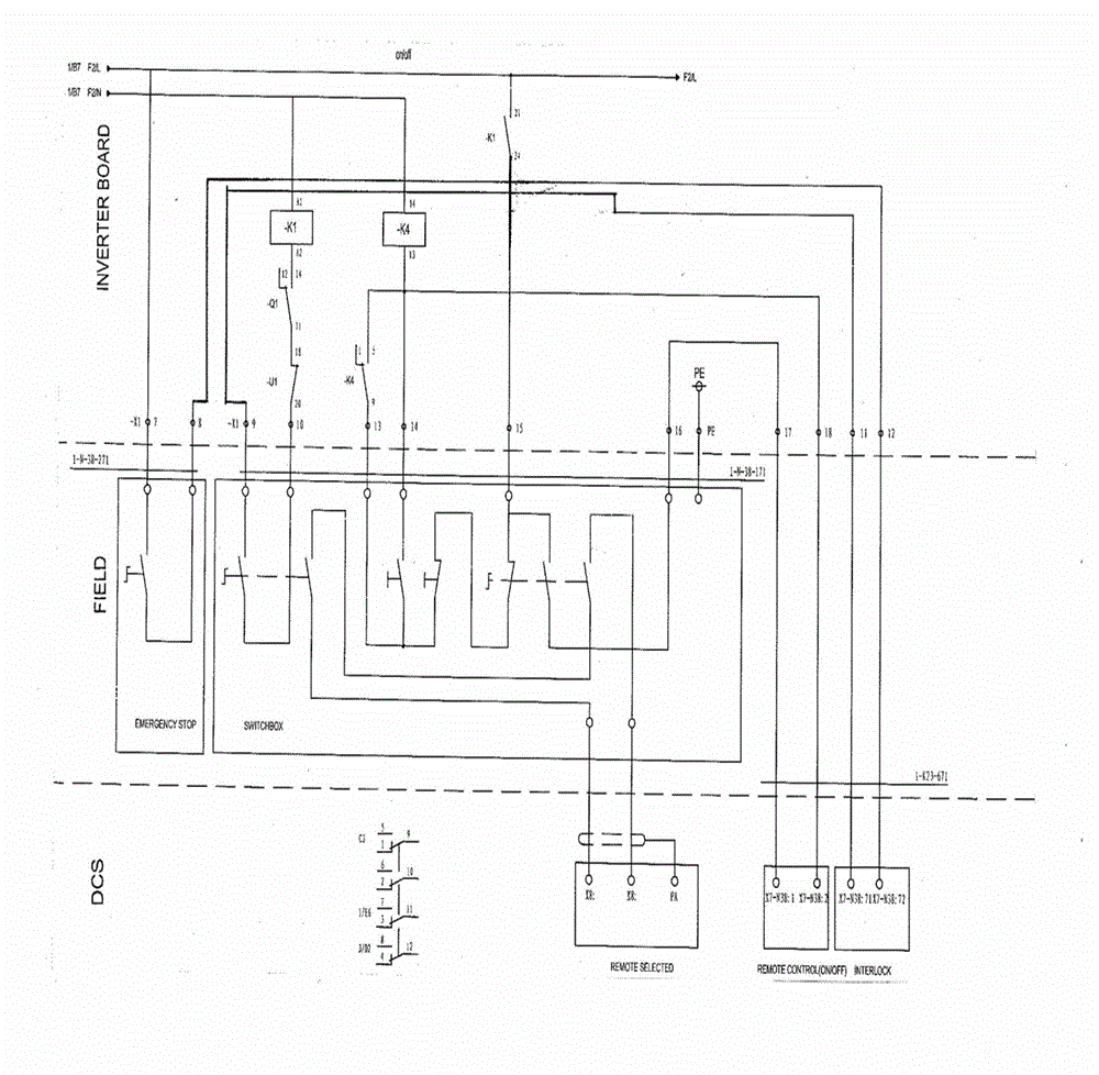
[0022] like figure 2 As shown, when the DCS system detects the derailment signal of the cha...


PUM


Abstract

The invention discloses a control device for a chain board conveying device. The chain board conveying device comprises a three-level conveying chain board, a vibration device and a control system and further comprises a non-contact position detection device, wherein the non-contact position detection device comprises a proximity switch and a locating plate fixed on a rotating shaft of a chain board derailment detection device. According to the control device, the position of the metal locating plate is detected by the change of magnetic field of the electromagnetic proximity switch; the control device is not provided with a directly contacted mechanical contact mechanism and not influenced by PTA (phosphotungstic acid) dust and surroundings when mounted at site; the position detection is more sensitive and reliable; and a protection signal can be triggered reliably once the chain plate derails so as to prevent a chain and the chain board from being damaged.

Description

technical field [0001] The present invention relates to a control device and method, and in particular to a control device and method for a chain conveying device of a polymerization device. Background technique [0002] The 1 / 2-088-Q-03 chain plate conveying device for the polymerization device is mostly used for PTA conveying. It is composed of three stages of conveying chain plates, vibration devices and control systems. Each stage of conveying chain plate is driven by a frequency conversion motor. The chain plate sprocket is equipped with a chain derailment protection device. In actual operation, there are often situations where there is no alarm after the derailment of the sprocket and the chain and disc are damaged, which greatly increases the maintenance workload and even affects the production and operation of the polyester plant in severe cases. [0003] Disassemble the chain derailment protection switch for inspection, and found that the switch is a mechanical rot...

Claims


Application Information

Patent Timeline
Patent Type & Authority Applications(China)
IPC IPC(8): B65G43/02
Inventor 李永强邱国全
Owner JIANGSU SHENJIU CHEM FIBER CO LTD
Learn More