
Device and method for testing buoyant force of buried pipeline

A technology for buried pipelines and testing devices, applied in measuring devices, force/torque/work measuring instruments, instruments, etc., can solve problems such as difficulty in finding theoretical methods, few consensuses, and different engineering conditions, and reduce Small test error, reducing the influence of boundary effects, reducing the effect of friction

Active Publication Date: 2015-04-29
BC P INC CHINA NAT PETROLEUM CORP +1
View PDF5 Cites 0 Cited by
  • Summary
  • Abstract
  • Description
  • Claims
  • Application Information

AI Technical Summary

Problems solved by technology

[0004] At present, there are many theoretical calculation methods on the buoyancy and uplift bearing capacity of oil and gas pipelines at home and abroad, but there is little consensus. Moreover, due to the different soil properties and engineering conditions in different places, it is difficult to find a suitable method for various complex calculation methods. conditional theoretical approach

Method used


Image

  • Device and method for testing buoyant force of buried pipeline
  • Device and method for testing buoyant force of buried pipeline

Examples


Embodiment Construction

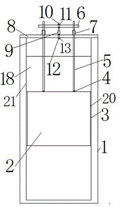
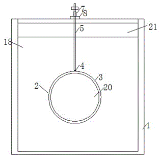
[0021] A kind of buoyancy testing device on buried pipeline, such as Figure 1 to Figure 2 As shown, including: test tank 1, pipe model 2, flexible filling material 3, connecting flange 4, connecting rod 5, loading beam 6, directional bearing 7, notch reaction beam 8, axial force gauge 9, the first type Connecting screw 10, first-type connecting nut 11, second-type connecting screw 12, second-type connecting nut 13, rock-soil model 18, pipe sealing steel plate 20, glass side 21, wherein:

[0022] The test tank 1 is provided with a glass side 21, the rock soil model 18 is filled in the test tank 1, the pipeline model 2 is buried, and the two ends of the pipeline model 2 are sealed with the pipeline model sealing steel plate 20, and the surface of the pipeline model sealing steel plate 20 is provided with a flexible filling material 3. The pipeline model 2 is connected to the connecting rod 5 through the connecting flange 4, and the connecting rod 5 passes through the directiona...


PUM


Abstract

The invention discloses a device and a method for testing the buoyant force of a buried pipeline. The device and the method are capable of accurately measuring the buoyant force of the pipeline in soil; an annular flexible filler material is arranged on the surface of the sealing steel plate of a pipeline model, so that the frictional force between the pipeline model and a test tank and the test error can be effectively reduced, and a rock-soil body model also can be effectively prevented from entering the gap between the sealing steel plate of the pipeline model and the wall of the test tank, thereby reducing the influence of the boundary effect and guaranteeing the test to be performed under the plane strain condition; glass side surfaces are formed on the test tank so that the displacement deformation conditions of the pipeline model and the rock-soil body can be effectively observed; and the displacement deformation of the pipeline and the soil body can be quantitatively analyzed by the particle image velocity measurement method.

Description

technical field [0001] The invention relates to a buoyancy test device and a test method for buried pipelines. Background technique [0002] With the rapid development of the economy, the development and utilization of energy has been paid more and more attention by people. In energy transportation, pipeline transportation has become an important way of oil and natural gas transportation due to its characteristics of large transportation volume, rapidity, continuity, economy, stability, safety, reliability, small area occupation, low investment and low cost. Due to the needs of rapid economic and social development in my country, the demand for energy continues to increase, and the construction of oil and gas pipeline projects is ongoing. Some special geological conditions, especially the deep soft soil, have brought great difficulties to the construction of pipeline projects. In areas with high water levels, pipelines often float up, which poses a huge hidden danger to en...

Claims


Application Information

Patent Timeline
Patent Type & Authority Patents(China)
IPC IPC(8): G01L5/00
Inventor 李江李强秦政先陈诚廖雍卿太钢康凯陈杰代卿
Owner BC P INC CHINA NAT PETROLEUM CORP
Learn More