

Device and method for testing buoyant force of buried pipeline
A technology of buried pipelines and testing devices, which is applied to measuring devices, force/torque/work measuring instruments, instruments, etc., can solve problems such as difficulty in finding theoretical methods, different engineering conditions, and few consensuses, etc., to achieve reduction Small test error, reduce the influence of boundary effects, reduce the effect of friction
- Summary
- Abstract
- Description
- Claims
- Application Information
AI Technical Summary
Problems solved by technology
Method used
Image

Examples
Embodiment Construction
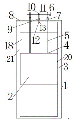
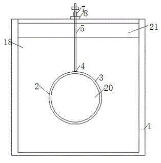
[0021] A kind of buoyancy testing device on buried pipeline, such as Figure 1 to Figure 2 As shown, including: test tank 1, pipe model 2, flexible filling material 3, connecting flange 4, connecting rod 5, loading beam 6, directional bearing 7, notch reaction beam 8, axial force gauge 9, the first type Connecting screw 10, first-type connecting nut 11, second-type connecting screw 12, second-type connecting nut 13, rock-soil model 18, pipe sealing steel plate 20, glass side 21, wherein:
[0022] The test tank 1 is provided with a glass side 21, the rock soil model 18 is filled in the test tank 1, the pipeline model 2 is buried, and the two ends of the pipeline model 2 are sealed with the pipeline model sealing steel plate 20, and the surface of the pipeline model sealing steel plate 20 is provided with a flexible filling material 3. The pipeline model 2 is connected to the connecting rod 5 through the connecting flange 4, and the connecting rod 5 passes through the directiona...
PUM
 Abstract
Description
Claims
Application Information