Water pressure test sealing device of anti-explosion motor base

A hydraulic test and sealing device technology, which is applied in the direction of measuring devices, instruments, scientific instruments, etc., can solve problems such as consumption of connection process bolts, troublesome assembly and disassembly, and bolt breakage, so as to prevent bolt breakage, save process bolts, reduce The effect of manufacturing costs

Inactive Publication Date: 2013-02-27
WOLONG ELECTRIC NANYANG EXPLOSION PROTECTION GRP CO LTD
View PDF3 Cites 6 Cited by
  • Summary
  • Abstract
  • Description
  • Claims
  • Application Information

AI Technical Summary

Problems solved by technology

Existing detection methods such as figure 1 and figure 2 Shown: During the hydraulic pressure test at the outlet box of the machine base, the waterway sealing structure is connected by multiple bolts to compress the hydraulic device, which is troublesome to assemble and disassemble, consumes a large number of connecting process bolts, and bolts will appear during use Broken in the base, difficult to remove

Method used


Image

  • Water pressure test sealing device of anti-explosion motor base
  • Water pressure test sealing device of anti-explosion motor base
  • Water pressure test sealing device of anti-explosion motor base

Examples


Embodiment 1

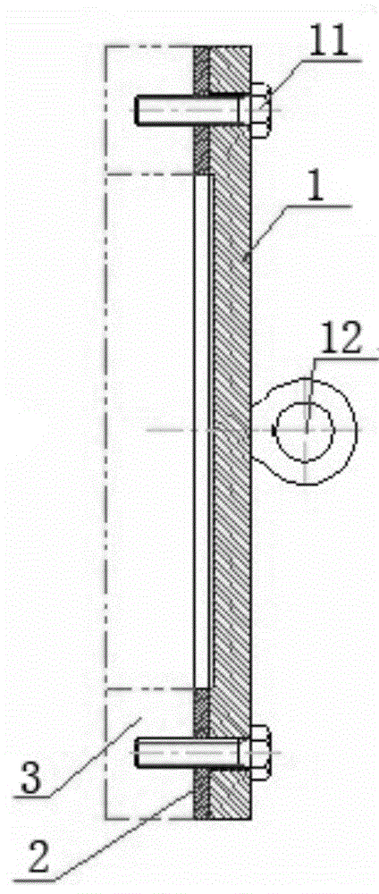
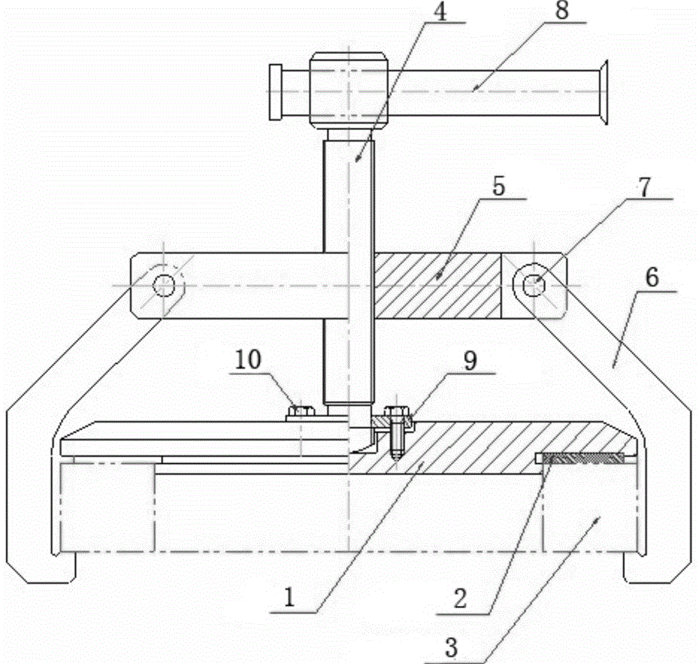
[0013] Embodiment 1: see image 3 , the junction box pressure plate 1 and the machine base junction box seat plate 3 are installed together, and the compression sealing ring 2 is used for sealing. The sealing device of the explosion-proof motor frame hydraulic test adopts a compression screw vertically facing the center of the junction box pressure plate 4. A beam 5 is threaded on the compression screw 4, and J-shaped hooks 6 are movable and installed symmetrically at the end of the beam 5. The other end of each J-shaped hook 6 can be hung on the base plate 3 of the junction box. bottom edge to ensure uniform force. It can be seen from the figure that the hook is hinged at the end of the crossbeam by the pin shaft 7 . In addition, a helical handle 8 is installed laterally on the leaking end of the compression screw 4 .

[0014] The end of the compression screw 4 in contact with the junction box pressure plate 1 is provided with a screw pressure plate 9, the screw pressure p...

Embodiment 2

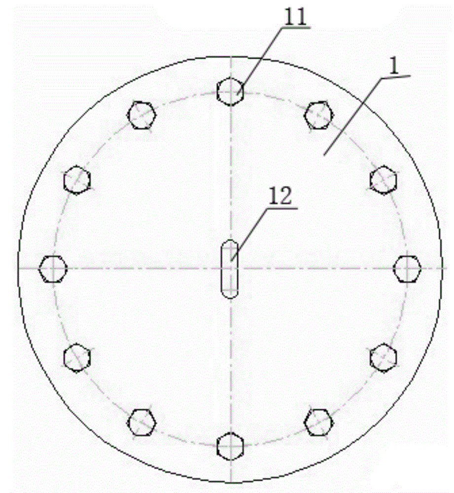
[0015] Example 2: see figure 1 , the content is basically the same as that of Embodiment 1, and the similarities will not be repeated. The difference is that there is another cooperative relationship between the compression screw 4 and the screw pressure plate 9: a concave hole is arranged in the center of the junction box pressure plate 1 groove, the center of the screw pressure plate 9 is provided with a through hole, the end of the compression screw 4 is arranged as a spherical surface and an annular groove is arranged near the spherical surface, and the annular groove is fixed in the center hole of the screw pressure plate 9 and can rotate relatively. The end spherical surface of the tightening screw 4 rotates and cooperates with the bottom of the groove at the center of the junction box pressing plate 3, and the screw pressing plate 9 at this moment plays a positioning role.

Embodiment 3

[0016] Embodiment 3: see figure 1 , the content is basically the same as that of Example 1, and the similarities will not be repeated. The difference is that the disc is used instead of the beam, the edge of the disc is evenly provided with notches, the J-shaped hook is matched and installed in the notch, and the J-shaped hook is matched with the notch. The inner side walls of the mouth are hinged together by a pin shaft 7 .


PUM


Abstract

The invention discloses a water pressure test sealing device of an anti-explosion motor base. The water pressure test sealing device comprises a pressing screw rod vertically aligning to the center of a pressing board of a wiring box; a beam or a disk and a J-shaped hook are in threaded connection with the pressing screw rod; and a spiral handle is transversely mounted at the exposed end of the pressing screw rod. With the adoption of the water pressure test sealing device provided by the invention, the sealing purpose can be realized by pressing a pressing board through the pressing screw rod. The water pressure test sealing device has the advantages of simple structure and convenience in installation. With the adoption of the water pressure test sealing device, the anti-explosion property of the base can be rapidly inspected, namely the sealing device can be rapidly assembled in a water pressure test, so that a large amount of process bolts can be saved; the bolt breakage phenomenon in production can be avoided; the production and manufacturing cost can be reduced; the quality is good; and the water pressure test sealing device is very beneficial to popularization and implementation.

Description

technical field [0001] The invention belongs to the technical field of inspection of accessory parts (base) of explosion-proof motors, and relates to a hydraulic test sealing device for explosion-proof motor bases. Background technique [0002] Explosion-proof motors are used as power sources to drive compressors, conveyors, roadheaders, water pumps, fans and other places where explosive gas or dust mixtures exist. Explosion-proof casings are the main components of the motors, and their explosion-proof performance directly affects the safety of equipment; Explosion-proof motor casings are generally made of castings or steel plates welded to form an independent explosion-proof cavity. After a motor casing is manufactured, necessary testing methods must be used to determine whether its explosion-proof performance meets the design and standard requirements. Explosion-proof motor manufacturing Plants generally use hydraulic presses for overpressure tests. [0003] As the rigid ...

Claims


Application Information

Patent Timeline
Patent Type & Authority Applications(China)
IPC IPC(8): G01N3/02
Inventor 贺良勇李新伟李磊胡彦能秦红河刘晓路尧卢连永杨小动王德义李建峰张翼李建雪张海红时晓阳
Owner WOLONG ELECTRIC NANYANG EXPLOSION PROTECTION GRP CO LTD
Why Eureka
Try Eureka