Time compensation device and method of photoelectric timer

A technology of time compensation and timer, which is applied to instruments, educational tools, teaching models, etc., and can solve the problem of inconsistency between timing duration and theoretical duration

Active Publication Date: 2013-02-27
LVLIANG POWER SUPPLY COMPANY STATE GRID SHANXI ELECTRIC POWER
View PDF5 Cites 4 Cited by
  • Summary
  • Abstract
  • Description
  • Claims
  • Application Information

AI Technical Summary

Problems solved by technology

[0009] In summary, this kind of photoelectric timer has the problem that the time length is inconsistent with the theoretical time length. The mai

Method used


Image

  • Time compensation device and method of photoelectric timer
  • Time compensation device and method of photoelectric timer
  • Time compensation device and method of photoelectric timer

Examples


Embodiment Construction

[0039] Below in conjunction with accompanying drawing, design and use of the present invention are further described.

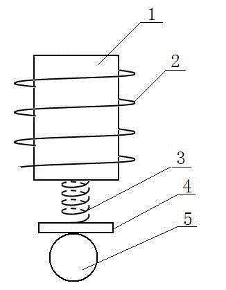
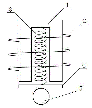
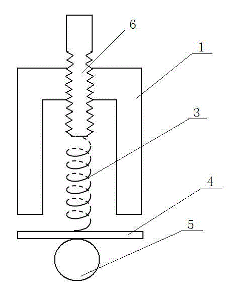
[0040] See attached figure 1 , is a design of the present invention, the electromagnet is composed of an iron core (1) and a coil (2) around the iron core (1), the upper end of the spring (3) is connected to the iron core (1), and the spring (3) A plate (4) made of soft magnetic material is connected to the lower end of the plate (4), and a weight (5) made of soft magnetic material attracted by the electromagnet is arranged on the lower part of the plate (4). Weight (5) can be iron ball. The length of the spring (3) is 2cm. Considering that the plate (4) has a certain mass, the spring (3) with a stiffness coefficient of about 100N / m is selected. The mass of the weight (5) is about 0.03Kg, and the mass of the plate is about 0.02Kg .

[0041] After the electromagnet is energized, the plate (4) moves upward, and the plate (4) attracts the weight (5) to m...


PUM

PropertyMeasurementUnit
Lengthaaaaaaaaaa
Stiffness coefficientaaaaaaaaaa
Lengthaaaaaaaaaa

Abstract

The invention discloses a time compensation device and method of a photoelectric timer and relates to a time compensation device for a free-fall timer. The photoelectric timer has the problem that timing duration and theoretical duration are not identical because of residual magnetism. According to the technical scheme provided by the invention, the time compensation device of the photoelectric timer comprises an electromagnet composed of an iron core (1) and a coil (2) wound on the iron core (1). The time compensation device is characterized in that the upper end of a spring (3) is connected with the iron core (1); the lower end of the spring (3) is connected with a plate (4) made of a soft magnetic material; and the lower part of the plate (4) is provided with a heavy object (5) made of a soft magnetic material and attracted by the electromagnet. The invention provides a novel technical scheme for solving the problem of time lag caused by residual magnetism in a free-fall motion.

Description

technical field [0001] The invention relates to a teaching aid for mechanics, in particular to a device for time compensation of a free fall timer. Background technique [0002] In the experiment of free fall, the method and device for measuring time have been very advanced. There is a relatively popular and more accurate photoelectric timing device like this: an electromagnet is used to attract a heavy object, which should be a soft magnetic material (so-called soft magnetic material). Magnetic material refers to: under the action of a magnetic field, the material is magnetic, and when the magnetic field disappears, the magnetic properties of the material also disappear. For example: iron), when the current of the electromagnet coil is cut off, the timing starts, and the weight passes through the photogate below (also When the signal is sensed by the photoelectric gate, the time of the process (from disconnecting the electromagnet coil to the weight reaching the photoelectr...

Claims


Application Information

Patent Timeline
IPC IPC(8): G09B23/10
Inventor 陈廷
Owner LVLIANG POWER SUPPLY COMPANY STATE GRID SHANXI ELECTRIC POWER
Why Eureka
Try Eureka