
Linear hollow spool valve

A valve and valve core technology, applied in the field of energy recovery systems, can solve the problems of easy leakage of the sealing system, increasing the cost and complexity of the energy recovery system, etc.

Inactive Publication Date: 2013-02-27
GENERAL ELECTRIC CO
View PDF7 Cites 2 Cited by
  • Summary
  • Abstract
  • Description
  • Claims
  • Application Information

AI Technical Summary

Problems solved by technology

This can increase the cost and complexity of the energy recovery system
The sealing system itself may be prone to leaks

Method used


Image

  • Linear hollow spool valve
  • Linear hollow spool valve
  • Linear hollow spool valve

Examples


Embodiment Construction

[0016] Various embodiments of the present invention will be described in detail below with reference to the accompanying drawings. It will be apparent, however, that these embodiments may be practiced without some or all of these specific details. In other instances, well known process steps or elements have not been described in detail so as not to unnecessarily obscure the description of the invention. The following exemplary embodiments and aspects thereof are described and illustrated in conjunction with apparatus, methods and systems that are intended as illustrative examples and not limiting in scope.

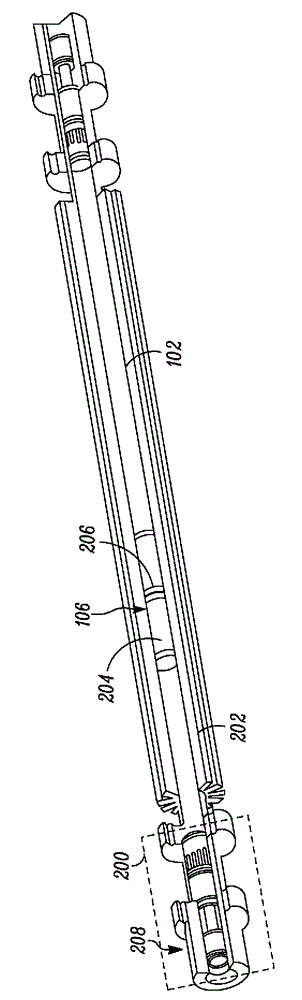
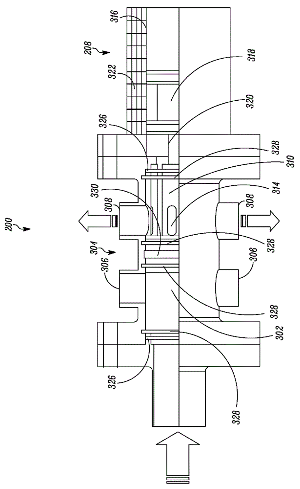
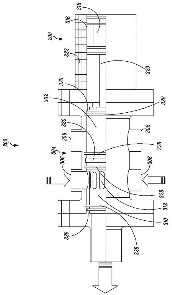
[0017] The present invention provides a valve system for a pressure exchange pipe of an energy recovery system. An energy recovery system is a device that utilizes the waste stream of a subsystem by exchanging energy from one subsystem to another to minimize the energy input to the overall system. In desalination systems, energy recovery systems can be used to transfer ...


PUM


Abstract

A valve system (200) for pressure exchanger tubes of an energy recovery system (100) is provided. The valve system includes a valve housing (304), a flow distributor (310), a hollow spool (302) and a sealing system, The valve housing may comprise a set of high-pressure ports (306) and a set of low-pressure ports (308). The flow distributor allows the flow to and from the set of high- pressure ports and the set of low-pressure ports within the valve housing. The hollow spool may be configured to reciprocate axially in a radial clearance between the valve housing and the flow distributor. The hollow spool may connect the pressure exchanger tube in fluid communication with the high-pressure ports or the low-pressure ports. The sealing system may be provided within the valve housing for imparting substantial hydraulic balance to the hollow spool.

Description

technical field [0001] Embodiments of the invention relate to an energy recovery system. More specifically, embodiments of the present invention relate to a valve system for an energy recovery system. Background technique [0002] An energy recovery system is a device that uses a stream of fluid at a higher pressure to pressurize another fluid at a lower pressure. Energy recovery systems are commonly used in desalination facilities to pressurize a feed stream by using high pressure concentrate. [0003] The energy recovery system may include a pressure exchange tube and a piston reciprocating inside the pressure exchange tube. In addition, a system of valves controls the flow of feedwater into the pressure exchange tube and the flow of concentrate out of the pressure exchange tube. One form of energy recovery system may include two or more pressure exchange tubes. Various valve systems are known in the art, such as rotary valve systems and linear valve systems. [0004]...

Claims


Application Information

Patent Timeline
Patent Type & Authority Applications(China)
IPC IPC(8): F16K11/07F16K31/122
CPCF16K11/07F16K31/122F16K11/0716Y10T137/8671
Inventor T.A.安德森M.R.沙P.P.博尚R.R.卡卢里S.M.N.巴特H.K.R.科梅怕利
Owner GENERAL ELECTRIC CO
Learn More