
Puller with positioning block

A positioning block and pull head technology, applied in positioning device, clamping, support and other directions, can solve the problems of slow processing speed, slow positioning speed of broaching, low workpiece accuracy, etc., and achieves high speed, low production cost and simple structure. Effect

Inactive Publication Date: 2013-03-06
JIANGSU CHUNLAN MACHINERY MFG
View PDF0 Cites 0 Cited by
  • Summary
  • Abstract
  • Description
  • Claims
  • Application Information

AI Technical Summary

Problems solved by technology

[0004] There is no positioning block on the slider in the prior art, so the broach cannot be positioned quickly, and the broach positioning speed is slow, resulting in slow processing speed and low precision of the processed workpiece

Method used


Image

  • Puller with positioning block
  • Puller with positioning block
  • Puller with positioning block

Examples


Embodiment Construction

[0020] The preferred embodiments of the present invention will be described in detail below in conjunction with the accompanying drawings, so that the advantages and features of the present invention can be more easily understood by those skilled in the art, so as to define the protection scope of the present invention more clearly.

[0021] The invention provides a pull head with a positioning block with simple structure, low production cost and high speed of positioning the broach.

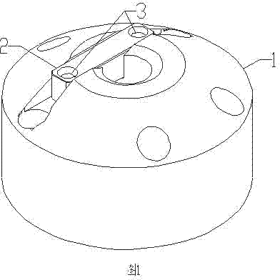
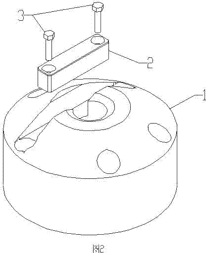
[0022] Such as figure 1 , figure 2 As shown, a slider with a positioning block, the slider includes a slider seat 1, a positioning block 2, and a bolt 3, the slider seat 1 is connected to the bolt 3, and the bolt 3 is connected to the positioning block 2.

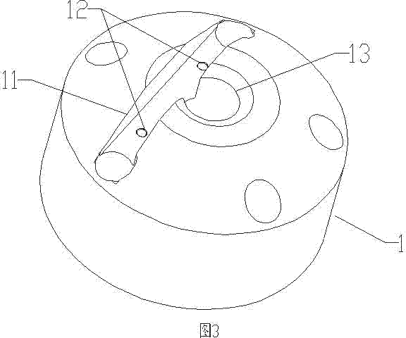
[0023] Such as figure 2 , image 3 As shown, the slider seat 1 is provided with a positioning block installation position 11, two threaded holes 12, and a broach hole 13. The positioning block installation position 11 is adapted to the p...


PUM


Abstract

The invention discloses a puller with a positioning block. The puller with the positioning block is capable of quickly conveniently positioning a broach on a broaching machine and comprises a puller seat, the positioning block and bolts. The puller seat is connected with the bolts which are connected with the positioning block, and is provided with a positioning block mounting position, two threaded holes and a broach hole. The positioning block mounting position is adaptive to the position of the broach hole, the threaded holes and the bolts are matched in size, the positioning block is provided with two through holes, the distance between the two through holes is equal to that between the two threaded holes, and the through holes and the bolts are matched in size. The puller has the advantages of simple structure, low production cost and high broach positioning speed and the like.

Description

[0001] technical field [0002] The invention relates to a slider, more precisely, a slider with a positioning block. [0003] Background technique [0004] There is no positioning block on the slider in the prior art, so the broach cannot be positioned quickly, and the broach positioning speed is slow, resulting in slow processing speed and low precision of the processed workpiece. [0005] Contents of the invention [0006] The present invention mainly solves the problems existing in the prior art, thereby providing a slider with a positioning block with simple structure, low cost and fast positioning. [0007] Above-mentioned technical problem of the present invention is mainly solved by following technical scheme: [0008] A slider with a positioning block, the slider includes a slider seat, a positioning block, and a bolt, the slider seat is connected with the bolt, and the bolt is connected with the positioning block. [0009] As a preferred embodiment of the pre...

Claims


Application Information

Patent Timeline
IPC IPC(8): B23Q3/18
Inventor 曹天虹桂容王崇高薛双红李曙薛厚勤
Owner JIANGSU CHUNLAN MACHINERY MFG
Learn More