Upper cutter shaft regulation device of amorphous strip precision shearing machine

A technology of amorphous strips and adjustment devices, which is applied in the direction of shearing devices, feeding devices, automatic control devices, etc., can solve the problem of inability to quickly and accurately adjust the gap between the upper and lower cutter heads synchronously, affect the shearing efficiency and cutting quality, and cannot Quickly and accurately adjust side clearance and other issues to achieve the effect of ensuring cutting accuracy and cutting quality, improving precision and reducing damage

Active Publication Date: 2013-03-06
宝鸡市精机设备有限责任公司
View PDF4 Cites 2 Cited by
  • Summary
  • Abstract
  • Description
  • Claims
  • Application Information

AI Technical Summary

Problems solved by technology

The lifting of the cutter shaft on the existing amorphous strip precision shearing machine is realized by manually rotating the hand wheel on the top of the left and right wallboards, and the left and right sides are individually adjusted, so the gap between the upper and lower cutter heads cannot be adjusted quickly and accurately synchronously. It will also cause damage to the supporting bearing of the upper cutter shaft; the axial adjustment is realized by prying the end face of the cutter shaft with a tool, which is not convenient to accurately control the axial displacement, and the side clearance cannot be adjusted quickly and accurately, and the upper cutter shaft will also be adjusted Damage, which affects shearing efficiency and shearing quality

Method used


Image

  • Upper cutter shaft regulation device of amorphous strip precision shearing machine
  • Upper cutter shaft regulation device of amorphous strip precision shearing machine
  • Upper cutter shaft regulation device of amorphous strip precision shearing machine

Examples


Embodiment Construction

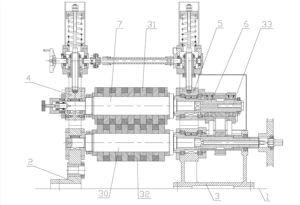
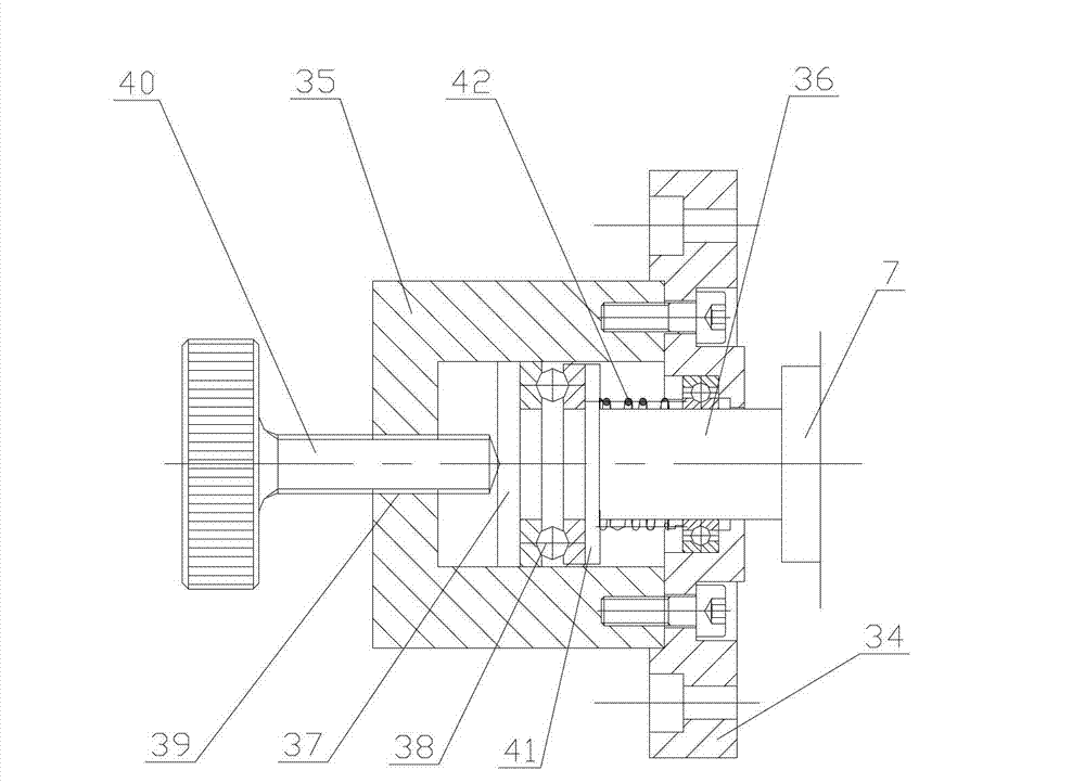
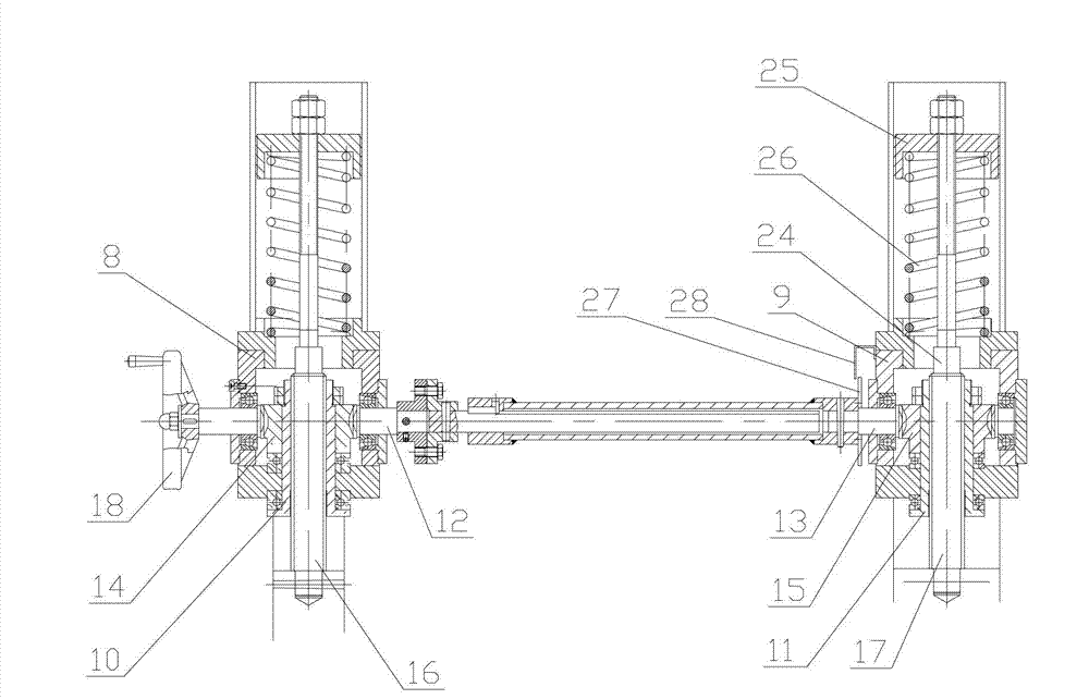
[0024] Attached below figure 1 -7 describes an embodiment of the present invention.

[0025] A synchronous lifting adjustment device for the upper cutter shaft of an amorphous strip precision shearing machine, including a base 1, a movable left wall panel 2 and a fixed right wall panel 3 are arranged on the table of the base 1, and the left wall panel 2 and the right wallboard 3 are symmetrically equipped with a left slider 4 and a right slider 5, the right slider 5 is equipped with a transmission shaft 6 through a bearing, and the right end of the upper cutter shaft 7 is inserted into the inner cavity of the transmission shaft 6 The left half is key-coupled with the transmission shaft 6, the left end of the upper cutter shaft 7 is installed on the left slider 4 through a bearing, and the upper ends of the left wallboard 2 and the right wallboard 3 are symmetrically fixed with a left adjustment support 8 and a right Adjusting support 9, the inner cavity of left adjusting supp...


PUM


Abstract

The invention provides an upper cutter shaft regulation device of an amorphous strip precision shearing machine. Firstly, a pair of a worm and a gear are utilized to synchronously drive and lift a lead screw, so that an upper cutter shaft generates displacement along the radial direction, a gap between an upper cutting disc and a lower cutting disc is regulated through radially and finely regulating the upper cutter shaft, a telescopic shaft coupling device is used to connect a pair of worms, a pair of gears can be enabled to synchronously rotate, and the movement of a left wall board cannot be influenced when the upper cutter shaft and a lower cutter shaft are dismounted; and secondarily, a side gap between the upper cutting disc and the lower cutting disc is regulated through the axial floating of the upper cutter shaft. The radial synchronous fine regulating and axial flexible fine regulating of the upper cutter shaft can be effectively ensured, accordingly, the gap and the side gap between the upper cutting disc and the lower cutting disc can be quickly and accurately adjusted, the working efficiency is increased, the damage to the cutting discs due to inappropriate cutter regulating is reduced, and accordingly, the shearing efficiency and shearing quality can be ensured.

Description

technical field [0001] The invention belongs to the technical field of strip shearing equipment, and in particular relates to an upper cutter shaft adjustment device of an amorphous strip precision shearing machine. Background technique [0002] Amorphous alloy strip is the key material for manufacturing amorphous alloy core transformers, so the requirements for the quality of amorphous alloy strips for making amorphous alloy cores are very high. Amorphous strip precision shearing machine is to use two dislocated disc knives on mutually rotating cutter shafts to cut the sprayed amorphous strip longitudinally according to a certain width specification, and then re-cut it under a certain tension. Neatly wound into rolls to obtain high-quality amorphous strips of different widths and specifications, meeting the requirements for making various amorphous alloy core transformers. [0003] The gap and side clearance between the upper disc knife and the lower disc knife must be adj...

Claims


Application Information

Patent Timeline
Patent Type & Authority Applications(China)
IPC IPC(8): B23Q15/22B23D19/06
Inventor 李振波贾满平卞亚洲
Owner 宝鸡市精机设备有限责任公司
Why Eureka
Try Eureka