Novel scraper conveyor

A scraper conveyor, a new type of technology, applied in the field of conveying equipment and new scraper conveyors, can solve the problems of increased production cost, decreased dust removal effect, blockage of main pipelines, etc. Consistent, high dust removal efficiency

Inactive Publication Date: 2013-03-06
JIANGSU CHANGJING ENVIRONMENTAL PROTECTION TECH
View PDF0 Cites 0 Cited by
  • Summary
  • Abstract
  • Description
  • Claims
  • Application Information

AI Technical Summary

Problems solved by technology

[0003] (1) Due to the use of circular pipes, the diameter of circular pipes is generally large, so that the resistance generated is large, dust enters from branch pipes, wood chips and other large particles enter the main conveying pipe, and a part of the deposit will occur. Over time, the main pipe will be blocked, making the conveying The air volume is greatly reduced, and when the air supply volume is reduced, wood chips and other large particles will settle in the circular main pipe, which will aggravate the blockage of the main pipe, resulting in a decrease in the dust collection efficiency of the ventilation and dust removal equipment, and the dust collection effect is poor. ;
[0004] (2) Once the existing conveying pipeline is completed, when the position of the ventilation and dust removal equipment needs to be changed, the layout of the dust collection pipeline will be disrupted, the balance will be destroyed, and the dust removal effect will be greatly reduced. It is very troublesome to move equipment and other machines, and the cost of moving is also greatly increased
[0005] (3) Using the existing circular conveying pipeline, sometimes the ventilation and dust removal equipment and other machines are not on the same pipeline, so when the machine is working, it is often necessary to open several dust collection lines at the same time, resulting in a significant increase in production costs

Method used


Image

  • Novel scraper conveyor

Examples


Embodiment

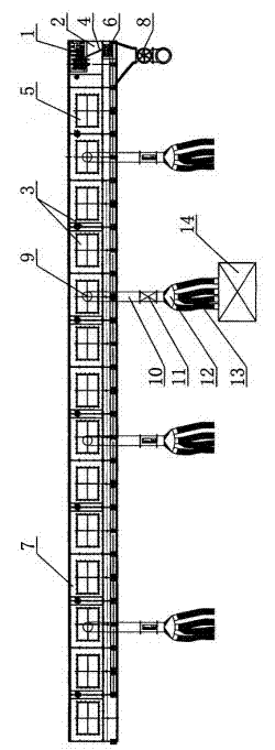
[0019] As shown in the drawings, a new type of scraper conveyor includes an organic head 2, an organic body 3, a chain 4 and a scraper 5, and a transmission device 6. The machine head 2 is provided with a power 1 and an unloader 8 . The fuselage 3 includes an organic tank housing 7 , and the scraper 5 is arranged in the tank housing 7 . The power 1 is connected with the chain 4 through the transmission device 6, and the scraper 5 is fixed on the chain 4. A plurality of air outlets 9 are opened on the machine tank housing 7, and branch pipes 10 are connected to the air outlets 9.

[0020] The branch pipe 10 is provided with a pneumatic valve 11, and the front end of the branch pipe 10 is equipped with a tuyere 12. The air nozzle 12 is connected with a dust suction hose 13 . The setting of pneumatic valve 11 can control the opening and closing of branch pipe 10 conveniently.


PUM


Abstract

The invention relates to conveying equipment, in particular to a novel scraper conveyor which comprises a head (2), a body (3), a chain (4), scrapers (5) and a transmission (6). The head (2) is provided with a power device (1) and an unloader (8), the body (3) comprises a closed trough shell (7), the scrapers (5) are arranged in the closed trough shell (7), the power device (1) is connected with the chain (4) by the transmission (6), the scrapers (5) are fixed onto the chain (4), a plurality of air openings (9) are arranged on the closed trough shell (7), and branch pipes (10) are connected to the air openings (9). Dust cannot be accumulated and deposited in the closed trough shell, blockage of the inside of the closed trough shell is prevented, a dust absorption effect is good, and the dust absorption efficiency is high. Besides, a fan on a dust absorption line can be used by an optional machine on the line, accordingly, energy is saved, the cost is lowered, and equipment assorted with the scraper conveyor can move conveniently.

Description

technical field [0001] The invention relates to a conveying device, in particular to a novel scraper conveyor. The present invention is mainly suitable for supporting use with ventilation and dust removal equipment and the like. The invention belongs to the technical field of mechanical equipment manufacturing and processing. Background technique [0002] The scraper conveyor can be used in various industries such as grain, oil, feed, etc., to realize the continuous conveying of bulk materials such as flour, feed, rapeseed, etc. The scraper conveyor can be used for horizontal conveying, and can also be used for inclined conveying. The scraper conveyor generally includes a machine head, a fuselage, a chain and a scraper, and a transmission device. The machine head is equipped with a power and an unloader, the body includes an organic tank housing, and the scraper is set in the machine tank housing, the power is connected to the chain through the transmission device, and th...

Claims


Application Information

Patent Timeline
Patent Type & Authority Applications(China)
IPC IPC(8): B65G19/18B65G45/10
Inventor 沈鑫森
Owner JIANGSU CHANGJING ENVIRONMENTAL PROTECTION TECH
Why Eureka
Try Eureka