
Descending bracket self-mobile model framework bridge fabrication machine

A technology of moving formwork and bridge-building machine, applied in the field of bridge-building machine, can solve the problems such as unavailability of advantages and high efficiency

Inactive Publication Date: 2013-03-06
SHANDONG LUQIAO GROUP
View PDF6 Cites 24 Cited by
  • Summary
  • Abstract
  • Description
  • Claims
  • Application Information

AI Technical Summary

Problems solved by technology

When the auxiliary lifting equipment cannot be reached, the construction conditions are limited, and the construction of the tidal flats, canyons, urban viaducts, cross-river, and sea-crossing bridge sites with continuous beam construction is difficult, its own advantages and efficiency cannot be brought into play.

Method used


Image

  • Descending bracket self-mobile model framework bridge fabrication machine
  • Descending bracket self-mobile model framework bridge fabrication machine
  • Descending bracket self-mobile model framework bridge fabrication machine

Examples


Embodiment Construction

[0030] Attached below figure 1 to attach Figure 13 The present invention will be further described.

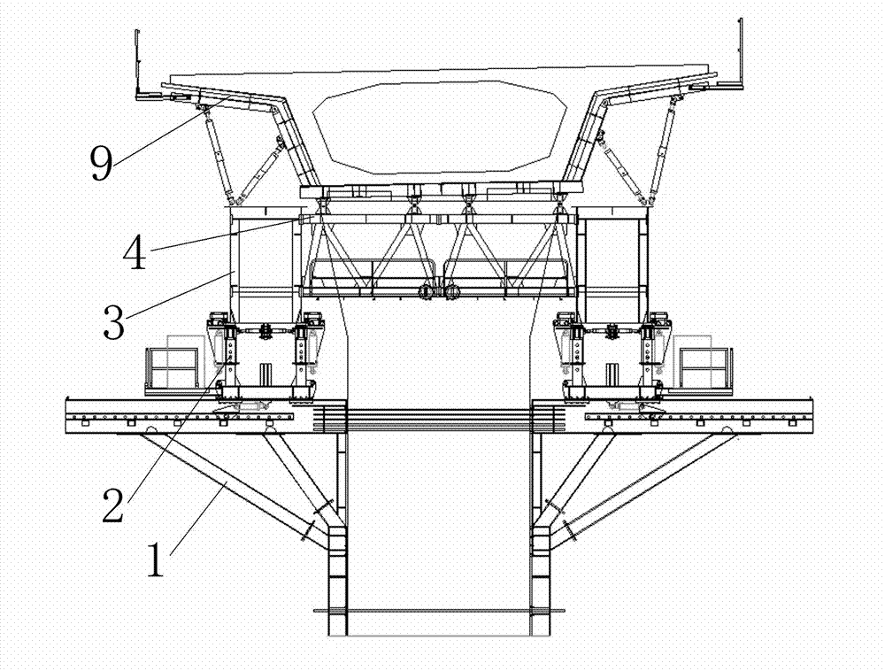
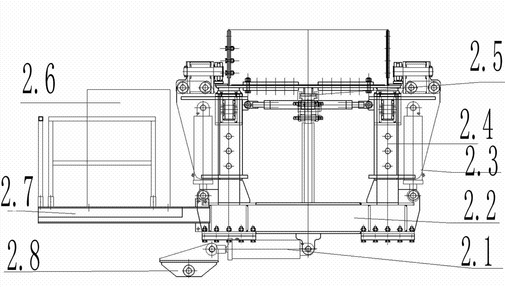
[0031] as attached figure 1 , attached figure 2As shown, the downward corbel self-moving formwork bridge building machine includes a corbel 1 supported on the pier body, a walking trolley system 2 installed on the top sliding surface of the corbel 1, a main girder 3, and two main girders. 3 and the beam 4 fixed on the main beam 3, the formwork system fixed on the beam 4 for supporting and adjusting the concrete box girder 9, the mid-hanging point beam 6 fixed on the concrete box girder, the nose beam 5, fixed on the bridge pier The front support beam system on 8.3 and the C beam 7 fixed on the main beam 3 and movable along the concrete box girder, the main beam 3 is supported on the traveling trolley system 2, and the traveling trolley system 2 drives the corbel 1 along the main beam 3 moves, the rear end of the nose bridge 5 is connected to the main beam 3, and its fron...


PUM


Abstract

The invention discloses a descending bracket self-mobile model framework bridge fabrication machine, and relates to a bridge fabrication machine. A middle lifting point cross beam takes place and finishes primary blanking together with a C beam and a traveling trolley system, so that conversion of a stressing system from the lower part to the upper part is realized. The front end of a nose bridge is driven by a front supporting cross beam system to be jacked in place. A bracket is driven by the traveling trolley system to move out transversely, move longitudinally to travel and move transversely to take place. The middle lifting point cross beam and the C beam together finish secondary blanking, a middle lifting point cross beam lifting rod is removed, the mobile die framework moves transversely to open, moves longitudinally to travel, moves transversely to close and jacks in place, and the C beam 7 is removed; and finally concrete is poured. Thus, through stressing system conversion of the bracket, the traveling trolley system, the middle lifting point cross beam and the C beam, the use at construction sites of continuous beams at sites of intertidal zones, canyons, urban viaducts, river-crossing bridges and cross-sea bridges with limited construction conditions and high construction difficulty, where the auxiliary hoisting equipment cannot reach, can be realized.

Description

technical field [0001] The invention relates to bridge construction equipment, in particular to a bridge building machine. Background technique [0002] In recent years, with the continuous growth of my country's highway and high-speed railway construction scale, the demand for advanced construction equipment and technology is getting higher and higher. The descending and ascending non-self-propelled mobile formwork bridge building machines have been widely used in domestic bridge construction since the 1990s. However, auxiliary lifting equipment is needed during construction, especially in the construction of non-self-propelled mobile formwork bridges with downward corbels, which need auxiliary lifting equipment to transport corbels and other components during construction. When the auxiliary lifting equipment cannot be reached, the construction conditions are limited, and the construction of the tidal flats, canyons, urban viaducts, cross-river, and sea-crossing bridge si...

Claims


Application Information

Patent Timeline
IPC IPC(8): E01D21/06
Inventor 王小山刘德建王殿学韩军霞
Owner SHANDONG LUQIAO GROUP
Learn More