Driver's cab suspension device with roll stabilizing means

a technology of suspension device and driver's cab, which is applied in the direction of roof, transportation and packaging, vehicle arrangement, etc., can solve the problems of reducing affecting the service life of the vehicle, so as to achieve the effect of simple design

Inactive Publication Date: 2014-10-30
ZF FRIEDRICHSHAFEN AG
View PDF8 Cites 12 Cited by
  • Summary
  • Abstract
  • Description
  • Claims
  • Application Information

AI Technical Summary

Benefits of technology

[0012]By virtue of the arrangement of the roll stabilizing system between the upper and lower cross-bridges and at the rear area of the driver's cab, all the components and assemblies of the roll stabilizing system can preferably be brought together directly in the area of the upper and lower cross-bridges and positioned between them. In this way not only is the rigidity of the suspension and roll stabilizing system increased (by virtue of the cross-bridges) in the rear area of the driver's cab, but also the arrangement of the components, in particular the hydraulic assemblies and the hydraulic lines between the hydraulic cylinders of the suspension system on the left and right sides, is better protected.
[0013]This also solves the fitting space problems that exist in the prior art in the front area of the driver's cab, and at the same time brings cost advantages due to the possible functional integration of the components and assemblies of the suspension system in the rear area of the driver's cab. Moreover, in particular because of the arrangement preferably of all the components and assemblies on and between the upper and lower cross-bridges, the suspension system can be designed as a relatively easily exchangeable module which, in turn, can have standardized interfaces for connection to the driver's cab and the chassis. This allows the suspension system to be adapted to the most varied vehicle groups or categories without any major modification complexity.
[0015]Pneumatic springs are advantageous in relation to low weight and because their characteristics can be varied simply by changing the air pressure. Moreover, the hydraulic cylinders of the roll stabilizing device can be arranged within the pneumatic spring elements, whereby considerable fitting space is saved, the number of assemblies is reduced and there is a mass reduction in relation to the suspension system as a whole.
[0016]In a further preferred embodiment of the invention the spring / damper arrangement comprises a single spring device, preferably a single pneumatic spring element, positioned between the cross-bridges and centrally in relation to the transverse direction of the vehicle. The suspension system then needs only a single spring device, in particular a pneumatic spring, for the rear area of the cab mounting. In this case, moreover, due to the cross-bridges there are no limitations regarding the spring properties or the rigidity of the rear cab mounting. Thus, this embodiment enables a further reduction of the number of individual components and assemblies, and hence corresponding mass and cost reductions.
[0019]Thanks to the (possibly controllable) pressure reservoirs and / or throttle elements the roll stabilizing or suspension system is also very flexible and can be used in a variable manner as necessary. This means that the suspension system can be used in various driver's cab variations without having to modify or change the size of the hydraulic elements in any fundamental way. Rather, in such a case all that is needed, is to adapt the system pressure or the pressure reservoir type, in order to adapt the suspension system for a different driver's cab variant.
[0020]Other preferred embodiments of the invention provide that an essentially horizontally acting transverse damping device or a Panhard rod is arranged between the upper and lower cross-bridges for horizontal stabilization. With the horizontally acting transverse damping device or with the Panhard rod, the degree of freedom of the driver's cab along the transverse direction of the vehicle can be fixed or controlled in a defined manner. Particularly when a Panhard rod is used, this gives a simply designed and robust means for stabilization in the transverse direction of the vehicle.

Problems solved by technology

However, the design of this known suspension system is comparatively complex and also entails fitting space problems, in particular since it is located in the forward area of the driver's cab where comparatively little fitting space is available for accommodating the components and assemblies of the suspension system.
Furthermore, the known suspension system has a comparatively large number of individual components and assemblies, which tends to entail high manufacturing and assembly costs.
Moreover, adaptation of the known suspension system to different types of vehicles and hence different spring, damping and rolling characteristics, is a comparatively complex process.

Method used


Image

  • Driver's cab suspension device with roll stabilizing means
  • Driver's cab suspension device with roll stabilizing means
  • Driver's cab suspension device with roll stabilizing means

Examples


Embodiment Construction

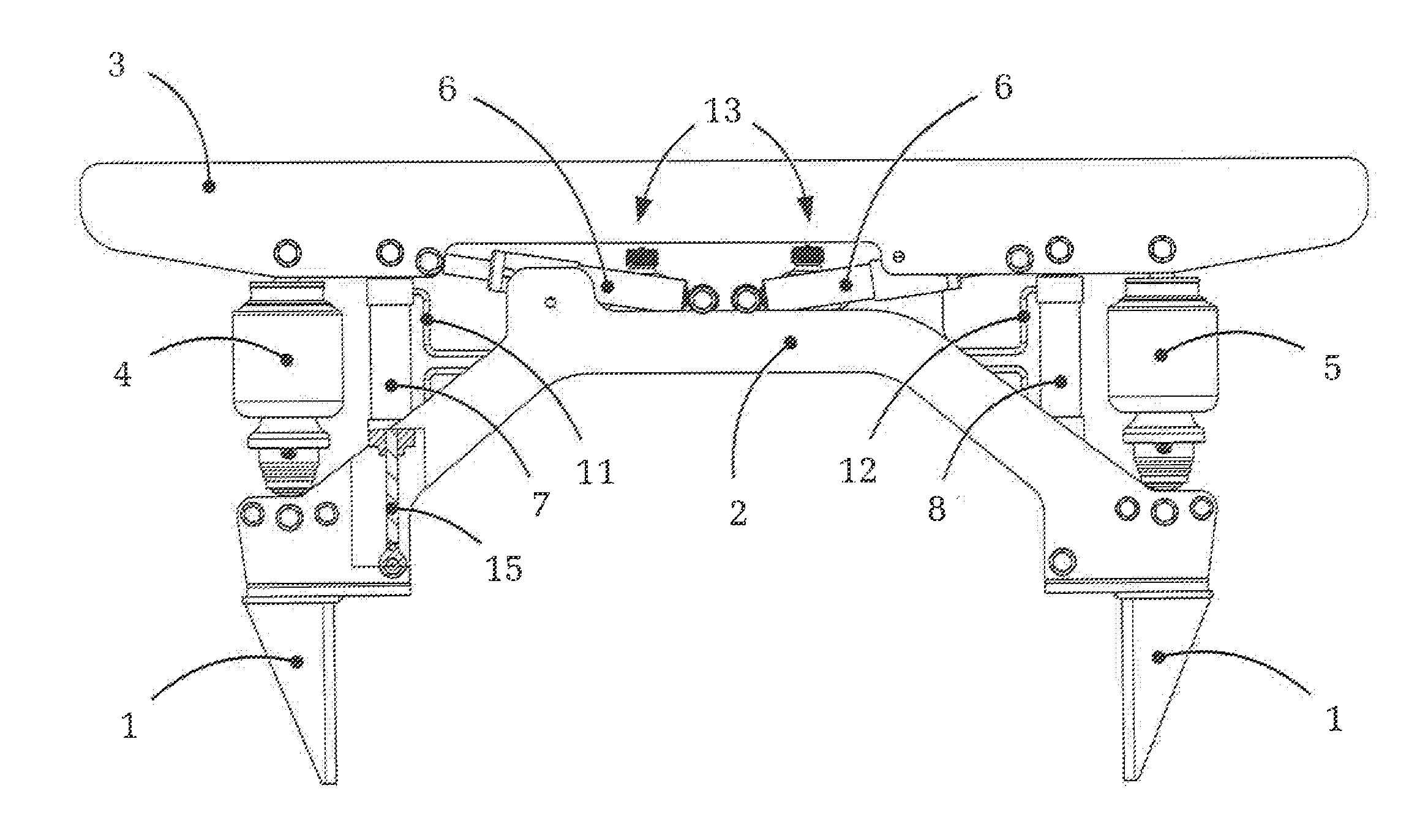
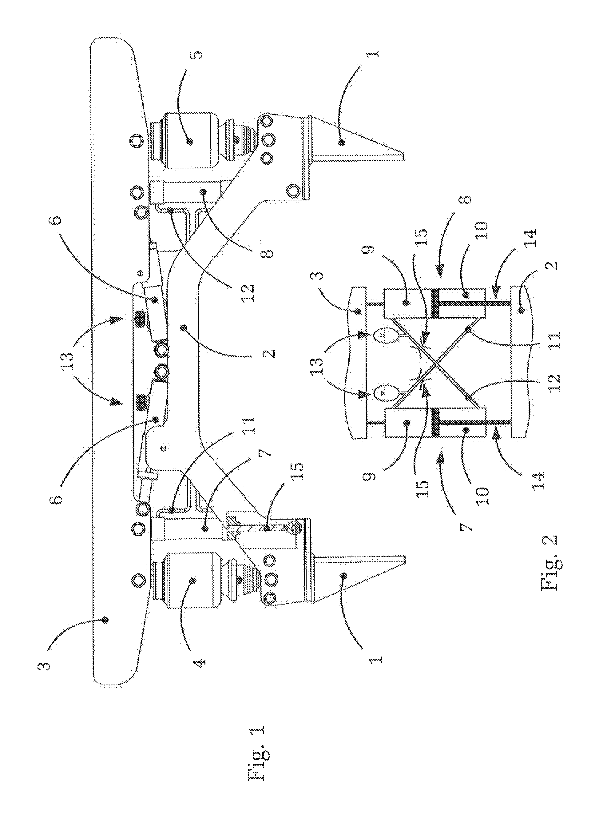
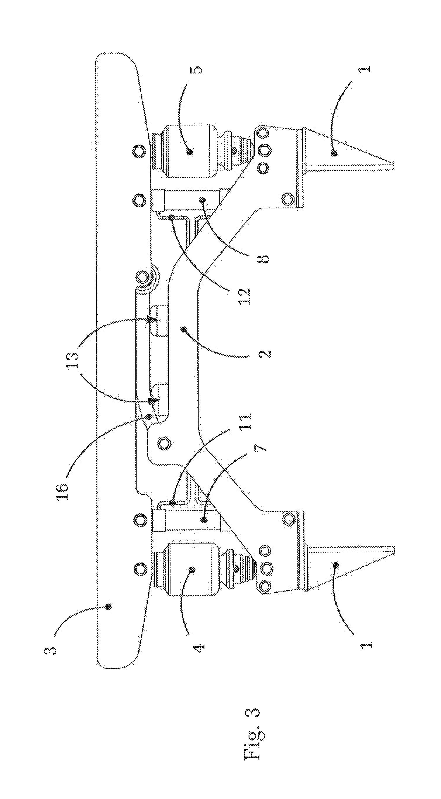
[0027]FIG. 1 shows an embodiment of a suspension system according to the present invention, for fitting between a truck chassis 1 and a driver's cab of the truck, looking along the driving direction from behind toward the rear of the driver's cab (not shown).

[0028]The figure shows the chassis 1 (only partially represented) of the truck on which, first, a lower cross-bridge 2 is fitted. In the rear area of the driver's cab is arranged a corresponding upper cross-bridge 3, which is connected to the driver's cab.

[0029]Between the upper cross-bridge 3 and the lower cross-bridge 2 are arranged the components or functional assemblies of the suspension system, which constitute a modular structure of the suspension system as a whole. Thus, the suspension system can be preassembled as a complete module and only then has to be connected to the chassis 1 and to the driver's cab, by means of corresponding standardized interfaces. In this way variants can be produced and the compatibility of the...


PUM


Abstract

A suspension system for the resilient / damped suspension of a driver's cab of a motor vehicle relative to the vehicle chassis. The suspension system has a spring / damper arrangement and a hydraulic arrangement with hydraulic cylinders on the right and left sides, relative to the driving direction. The hydraulic cylinders are connected in a cross-over manner to form a roll stabilizing device. The suspension system has an upper cross-bridge that is arranged on the driver's cab and a lower cross-bridge that is arranged on the vehicle chassis. The spring / damper arrangement and the hydraulic arrangement are positioned between and connected to the upper and lower cross-bridges.

Description

[0001]This application is a National Stage completion of PCT / EP2012 / 075931 filed Dec. 18, 2012, which claims priority from German patent application serial no. 10 2012 200 670.2 filed Jan. 18, 2012.FIELD OF THE INVENTION[0002]The invention concerns a suspension device for the resilient and shock-damping suspension of a driver's cab of a motor vehicle relative to a vehicle chassis.BACKGROUND OF THE INVENTION[0003]Suspension systems of the above type are used, for example but by no means exclusively, in trucks, agricultural vehicles or heavy-good vehicles. Since in such vehicles the spring and damper characteristics of the spring / damper units of the chassis have to be chosen to be comparatively large because of the considerable vehicle weights and because of the large unsprung masses in the chassis, road surface irregularities or even vibrations from the axles and the drive-train are first to a considerable extent transmitted to the chassis via the axle suspension. For that reason it ...

Claims


Application Information

Patent Timeline
Patent Type & Authority Applications(United States)
IPC IPC(8): B62D33/06
CPCB62D33/0608B60G99/002B60G99/004B60G99/008
Inventor SCHAUER, MICHAELEISMANN, JENSHELM, EIKEQUAING, MATTHIASBUBLIES, HOLGER
Owner ZF FRIEDRICHSHAFEN AG
Why Eureka
Try Eureka